

BMW 3-Series and 4-Series Forum (F30 / F32) | F30POST
>
DIY: F30 Active Blind Spot Detection(Lane Change Warning) Retrofit

| 03-18-2016, 01:07 PM | #1 |
|
Major
 1140
Rep 1,136
Posts |
DIY: F30 Active Blind Spot Detection(Lane Change Warning) Retrofit
Hello all! While most people seem to share the consensus that the F30 is relatively well designed to avoid blind spots in the mirror, I had become used to having the Blind Spot systems on several other vehicles I have driven or been a passenger in over the past year or so, and so I decided to retrofit the factory Lane Change Warning system into my car. This will be a lengthy write up, just because there are many optional steps that not everyone will need, so you can read it and determine what parts you would need and go from there. Despite the length and detail of the write-up, the total time to do this should not be more than a day, even if you are being very thorough.
Total cost for this ended up being around $900 USD, not factoring the extra money recovered from selling the original parts removed from the car. Patience and waiting for finding good deals on the auction sites makes it much more reasonable than buying parts new. DISCLAIMER: As will all DIY projects, undertake this at your own risk. I am not responsible for anything that happens to you or your car! This retrofit will potentially require you to remove your airbag and your steering wheel, so if you are not comfortable with doing this, please find someone who is willing to assist you with that part of the retrofit. This system does provide visual/tactile alerts to vehicles that may be in your blind spot, however you are still responsible for ensure safe clearance between other vehicles when changing lanes. With that said, on to the write-up! Pre-Requisites: At a minimum, the only thing you really need on the vehicle if you are not swapping the mirrors would be the Automatic Exterior Mirrors. Additionally, if you do not have the Heated Steering Wheel Option or the Lane Departure Warning/Driving Assistant, you will possibly need to replace your Steering Column Switch Cluster. In the event that you do have the Heated Steering Wheel option already, I recommend that you check to see if you have the Vibration Generator. To check this, you would need to remove the Airbag from the steering wheel, and then look in the lower left corner of the opening to see if the Vibration Generator is present. You will also need the E-Sys software for coding your car, as well as ISTA/Rheingold for initializing first the FlexRay lines and then initializing the Radar Sensor units. Parts List: (Note: Part #’s may vary per vehicle. Parts listed below are for a US F30 sedan. Check RealOEM or ETK to confirm correct Part #’s for your vehicle) Mirrors: I recommend you try to find them used, if possible. You are looking for the mirrors which already have the Lane Change Warning Indicator(White Triangle). In the event you cannot find them used, you would need to order the Mirror Electronics below, which are very pricy and also are typically on backorder from BMW. Also, be aware that there are two different types of mirrors, those with the matte black look and those with the High Gloss Black Shadow line(found on Sport and M-Sport models). The exterior look of the mirror you buy does not really matter, as you can always take the wiring from the new mirror and reuse your old mirror, you would just need to order the replacement Supporting Rings. Minimum Required Parts: - Lane Change Radar Unit, Master – There are several part #’s available for this which can be found here, they are all interchangeable. However, try to get them as close together date-wise as possible. I ended up having to do a software update since my Master Radar Unit was much older than my Slave Radar Unit, however they function perfectly fine now despite the difference in production date - Lane Change Radar Unit, Slave – Same as above, part #’s can be seen on the link - Radar Screen, Left - 66326794270 - Radar Screen, Right - 66326794269 - Radar Mount Bracket (left and right included) - 66326795928 - Hex Nut with Plate - 07147155614 x2 - Driver Assist Switch – There are several part #’s available for this depending on other options you have, which can be viewed here. These can be found much cheaper on eBay than buying new, and it doesn’t matter which switch you get as long as it has the Lane Change Button - 4-Pin Connector (for Driver Assist Switch) - 61138380696 - 12-Pin Connector (for Lane Change Radar Units) – 61138373630(Qty. 2) - Socket Contact Wiring Pins w/ grommets for Lane Change Connectors – 61130005199(Qty. 12) - Socket Contact Wiring Pins for FEM connections and Driver Assist Switch – 61130005197(Qty. 15) - OEM Wire Taps for power and ground connections to Lane Change Radar – 61138364566(Qty. 3) Potentially Optional Parts: - Mirror Electronics, Left – 67137438145 (Only needed if you are not swapping the mirrors) - Mirror Electronics, Right – 67137438144 (Only needed if you are not swapping the mirrors) - Mirror Supporting Ring, matte black, Left – 51167302409 (High Gloss Version - Part # 51167302411) - Mirror Supporting Ring, matte black, Right – 51167302410 (High Gloss Version - Part # 51167302412) - Vibration Generator (only if not already present in your steering wheel) – 32337849416 (M-Sport Steering Wheels) or 32336787451 (Non M-Sport Steering Wheels) - Double Leaf Spring Contact – 61130007437 (Only needed if you are replacing your Steering Column Switch Cluster and do not have wires in Pin #9 and Pin #11 in the listed steps of replacing the column included further down in the instructions) - Steering Column Switch Cluster – This is only needed if you have to replace this part if you do not already have the Heated Steering Wheel or Lane Departure/Driver Assistant options. There are 7 different versions of this part available based on the other options your car has. List of part numbers can be found here - Control Unit, Steering Wheel Electronics (Only needed if you do not already have Heated Steering Wheel or Lane Departure/Driver Assistant) – There are different part numbers for this depending on if you have the M-Sport Steering Wheel or not - Connecting Line, Steering Wheel (This will be needed only if you do not already have the Vibration Generator) – Again, there are different part numbers depending on what other options and steering wheel you have - Trim Cover, Driver Assistance Switch – Different Part Numbers based on your interior color, #1 on the parts list seen here- This is optional depending on if you already have the storage box on the left side of the dash under the headlight switch, and if you want to replace it to mount the switch in its’ OEM space. As you read further, you will see where I “tucked” my switch since once the system is turned on, you won’t need to turn it on/off again unless you have to re-encode the FEM, and I didn’t want to lose the extra storage space from the bin 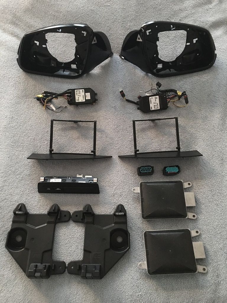 Tools Required: - Socket Set with 16mm(Deep if possible) , 10mm(Deep), 8mm, and 6mm sockets - Hex/T set – This project requires sizes ranging from T-10 to T-35/T-40 - Phillips Head Screwdriver - Flat Screwdriver/Pry tool for removing the plastic expanding rivets - Very Small Flat Screwdriver - Wire Stripper - Wire connectors/solder depending on your preference - 4 colors of 18 gauge wiring (I used Black, Red, Yellow, and Blue. You can use whichever colors you like, however for reference, I will refer to the colors I used in the write-up) - Standard black electrical tape - 3 additional colors of electrical tape (I used Red, Yellow, and Blue. You can use whichever colors you like, however for reference, I will refer to the colors I used in the write-up) Prep Work: - Disconnect Negative Terminal from Battery – Make sure all doors are unlocked, front windows are down, and trunk is open first - Remove the Rear Bumper – Steps can be seen in my Rear PDC Retrofit Thread - Remove Driver and Passenger Side under dash trim panel - Remove all floor trim pieces along the Passenger side of the vehicle - Remove the Passenger Side Trunk Lining - Remove the Passenger side trim piece the covers the FEM Installing the Radar Units/Brackets: After removing the bumper, you will be able to see the opening on each side below the tail lights where the radar brackets will be installed - Place the left bracket (marked with an “L”) on to the bolt post with the tabs inserted into the openings on the Bumper Center Guide, as shown below 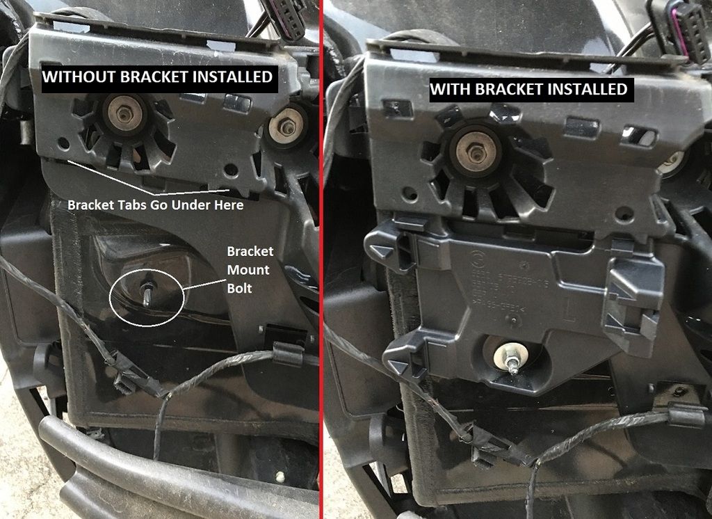 - Using one of the Hex Nut w/Plate, secure the bracket to the vehicle - Take the Left Radar (HC2 Slave) and the Left Screen, and attach the screen to the radar unit - Once the screen it attached to the radar, place the radar unit into the bracket inserting the end with 2 tabs into the bracket, then press the unit towards the car until it clicks into place, as shown below 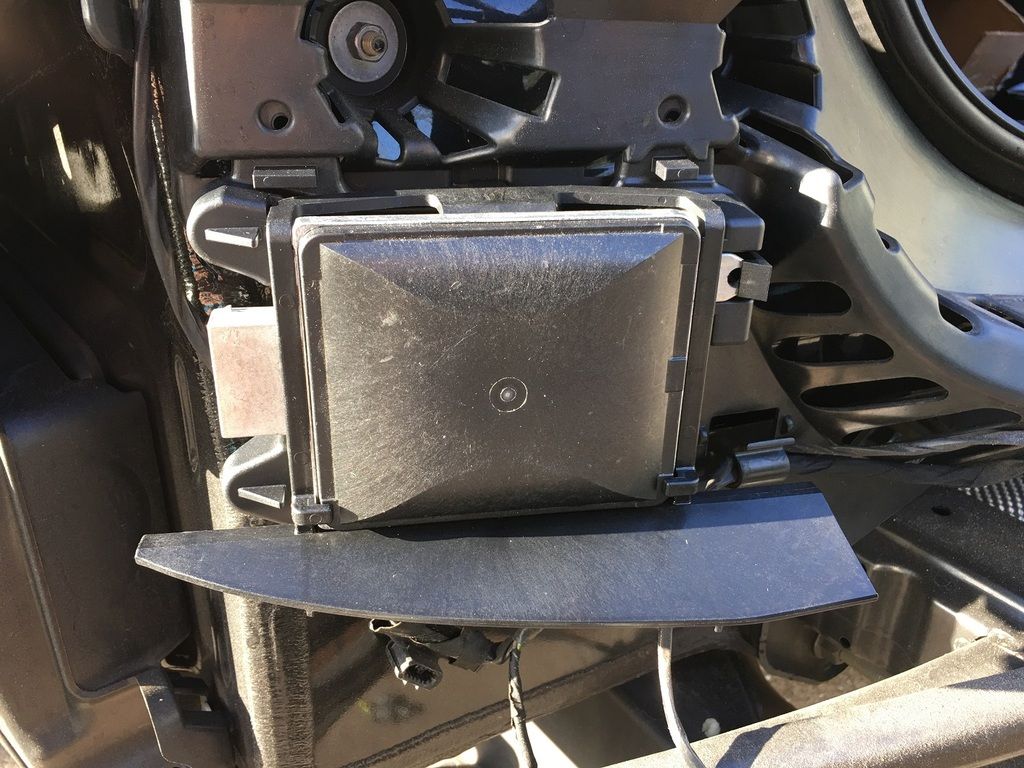 - Repeat for the right side radar unit (HC2 Master) Creating the Radar Unit Wiring: To start, we will be creating the wiring that connects from the Left Radar (HC2 Slave) to the Right Radar (HC2 Master). For reference, you will be starting on the Driver’s Side (Left) of the car for this harness. - Take 4 of the Socket Contacts w/ Grommet (61130005199) and use a small amount of the colored electrical tape to mark each wire near the connector. Then, insert them into one of the 12-pin connectors (61138373630) into the following slots: - Pin 5 – Can Low (Yellow) - Pin 9 – Power (Red) - Pin 10 – Ground (Black) - Pin 12 – Can High (Blue) - Once the pins have been inserted, connect the colored 18-gauge wire to each matching color-marked socket contact (red to red, blue to blue, etc.) and run about 6 feet of length for the 4 wires. Make sure to check to ensure you have enough length to comfortably run the wires along the existing harness to the Passenger Side Radar Unit before cutting the length. - Connect this 12-pin connector the Left (Driver’s Side) Radar Unit (HC2 Slave) - Using black electrical tape(or your preference of adhesive wrapping material), wrap the length of the wires starting at the 12-pin connector to near the ends of the colored 18 gauge wires to make a secure harness to prevent loose/exposed wires - Take the ends of the colored 18 gauge wires and connect 4 of the Socket Contacts w/ Grommet (61130005199), making sure to attach a small piece of matching colored electrical tape near the contact end so you will be able to identify which wire is which. Once you have connected the 4 Socket Contacts, finish wrapping the harness from the step above - Now, take the remaining 12-pin connector (61138373630) and insert the 4 wires from the harness into the following Pin Slots: - Can Low (Yellow) to Pin Slot #1 - Power (Red) to Pin Slot #11 - Ground (Black) to Pin Slot #12 - Can High (Blue) to Pin Slot #2 The wiring between the two Radar Units is complete; now, we will create the wiring that runs to the inside of the vehicle. - In order to gain access to the wire entry point, you will need to remove the Passenger Side Bumper Guide by removing the bolts/nuts as shown below, then press in at the top two tabs and pull down: 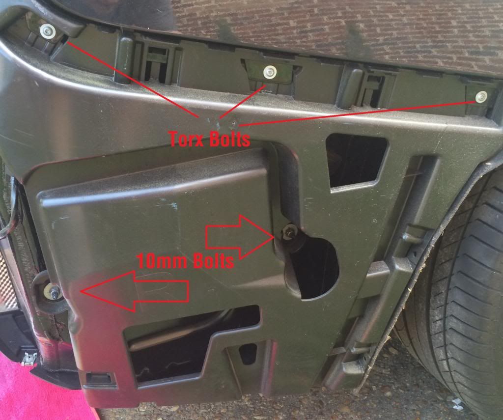 - Start by making another harness of the 4 colored 18 gauge wires by wrapping the wires with electrical tape(or your preference of adhesive wrapping material) - From the inside of the Passenger side Trunk right above the battery, locate the existing large grommet where the wires run to the outside of the car - On that grommet, you will see an indented hole to be used for running repair wires, similar to the ones used for the front firewall on the Surround View retrofit - Using a large screwdriver or drill bit, puncture through the grommet in that opening to make a hole for the new wire harness to run through - Once you have made the opening, run the wires through the opening starting from inside the car, as shown below: 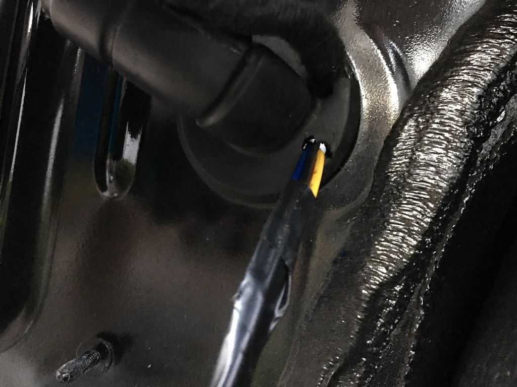 - Run the wires to the Passenger Side(Right) HC2 Master 12-Pin Connecter that you made above - Take the ends of the colored 18 gauge wires coming from inside the car, and connect the remaining 4 Socket Contacts w/ Grommet (61130005199), making sure to attach a small piece of matching colored electrical tape near the contact end so you will be able to identify which wire is which. Once you have connected the 4 Socket Contacts, finish wrapping the rest of this part of the harness - Now, insert the 4 wires from this part of the harness into the following Pin Slots on the Passenger Side HC2 Master 12-Pin connector: - FlexRay Signal 1 (Yellow) to Pin Slot #5 - Power (Red) to Pin Slot #9 - Ground (Black) to Pin Slot #10 - FlexRay Signal 2 (Blue) to Pin Slot #6 Double check that all wires are in place, and then connect the connectors to the Radar Units. Once you have completed this, you are ready to move on to connecting the wiring from the harness. Power Wire (Red): - Take the red Power wire from the Master Radar harness you created and run it along the factory wiring to the Rear Power Distribution (Fuse) Block. - Undo the 10mm hex nut holding the Fuse Block in place, then turn it over to view the wires on the backside - You will be looking for Fuse Slot F148. On some vehicles, there may already be a wire in this fuse spot as it is already related to the vehicle suspension. This will be a Green w/ Blue stripe wire. - Using the OEM Wire Tap, connect the Red Power Wire to the Green/Blue wire from Fuse Slot F148, as shown below: 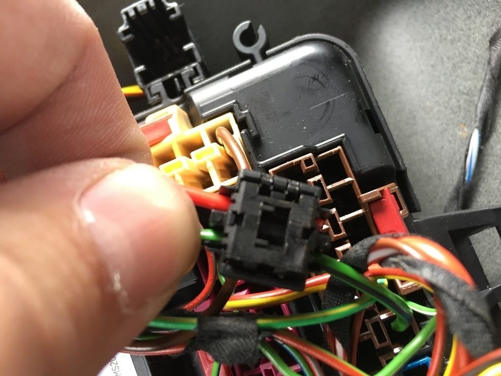 Ground Wire (Black): - Take the black Ground Wire from the Master Radar harness you created and run it along the factory wiring to the grounding point above the right side of the trunk area. - Connect the black Ground wire to a similar sized Brown wire coming from the Grounding Point using an OEM Wire Tap, as shown below: 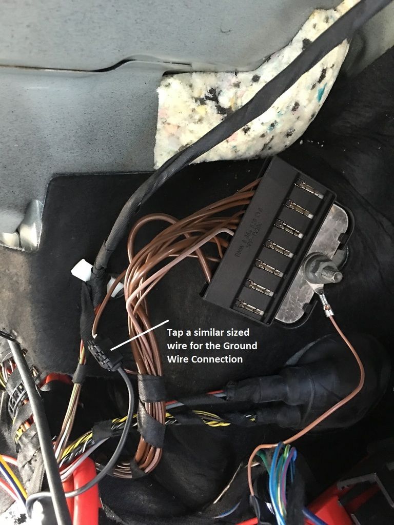 FlexRay Signal Wires: - Take the Blue and Yellow FlexRay Signal Wires from the Master Radar Harness you created and begin to make a harness with them by wrapping them with electrical tape or another adhesive wrapping material - Run these two wires along the Passenger (Right) side of the car to the FEM module located under the Passenger Side dash area - Take the ends of the 2 colored 18 gauge wires and connect a Socket Contact (61130005197) to each wire, making sure to attach a small piece of matching colored electrical tape near the contact end so you will be able to identify which wire is which. - Locate the 54-pin Connector A173*8B on the FEM, and connect the two wires in the following pin slots: - FlexRay Signal 1 (Yellow) to Pin #10 - FlexRay Signal 2 (Blue) to Pin #9 Creating the FlexRay Loop: - This work will be done within the same connector(A173*8B) from the FEM. Check to see if you have Pink/White and Green wires already occupying Pin Slots 23, 24, 27, and 28. If you do, you can skip this section - Assuming you do not have those wires already present, take 4 of the Socket Contacts (61130005197) and trim them to about 4” in length each - Connect 2 contacts together at the wire end and secure using electrical tape or solder. Repeat for the other 2 contacts so that you have 2 cables - Take the first cable, and insert one end into Pin Slot #23. Connect the other end of this cable to Pin Slot #27 - Take the second cable and insert one end into Pin Slot #24. Connect the other end of this cable to Pin Slot #28 - When done, it should resemble the picture below: 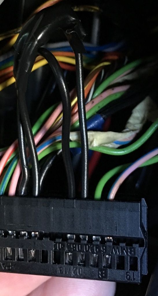 Installing/Wiring the Driver Assistance Switch: As mentioned in the Parts List, this step may vary depending on if you already have a Driver Assistance Switch in your car, or if you want to replace the storage box to have access to the switch at all times, which is not necessary since once this system is on, it will remain on unless you have to have the FEM re-coded. The steps below will outline how to run the wiring, and the picture below shows where I “tucked” the switch by zip-tying the wiring to the dash mount to secure it in place, so the switch can still be accessed but does not interfere with the A/C Vent or the Storage Bin: 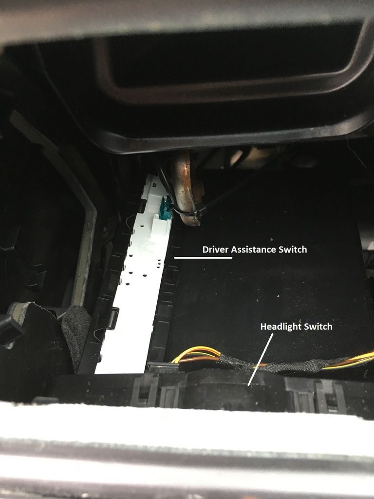 - Take 3 of the colored 18 gauge wires (Red, Black, and Yellow) and begin to make a harness by wrapping the 3 wires together using electrical tape or another adhesive wrapping material - Starting from the Passenger Side area under the dash, push the wire harness through to the Driver Side under dash area - Gently pull the A/C Vent out to remove it to gain access to the area behind the headlight switch - Bring the wires up to the opening made by removing the A/C vent - Take the ends of the 3 colored 18 gauge wires and connect a Socket Contact (61130005197) to each wire, making sure to attach a small piece of matching colored electrical tape near the contact end so you will be able to identify which wire is which - Take the 4-pin Connector (61138380696) and insert the 3 Socket Contacts into the following pin slots: - Power (Red) to Pin Slot #1 - Ground (Black) to Pin Slot #4 - Signal (Yellow) to Pin Slot #2 - Return to the Passenger Side end of the harness and route it behind the carpet to the FEM - Take the ends of the 3 colored 18 gauge wires and connect a Socket Contact (61130005197) to each wire, making sure to attach a small piece of matching colored electrical tape near the contact end so you will be able to identify which wire is which. - Locate the 54-pin Connector A173*7B on the FEM, and connect the 3 wires in the following pin slots: - Power (Red) to Pin Slot #37 - Ground (Black) to Pin Slot #39 - Signal (Yellow) to Pin Slot #38 Swapping the Mirror Wiring/Shroud Trim: Depending on how you went about getting your mirror parts, you may not need to follow all of the steps in this process. Read through it to see what steps are applicable to you. If you got the entire mirror assembly online and do not need to swap between Matte/Gloss, you can just remove the old mirror and install the new mirror without needing to do anything else - To get started, you will need to remove the door panel on the vehicle. This is a relatively simple process, with tutorials available on the internet. Simply pry off the trim piece on the door(the CF-wrapped piece shown in this image, then remove the two Hex screws inside the handle. Once those are removed, start at one end and begin prying the door panel loose. Once the panel is loose, you can lower it down, you do not need to remove/disconnect any switches/connectors. Next, loosen the trim piece that houses the tweeter by pulling it towards you, this will expose the mirror connector and 3 Hex Bolts that secure the mirror to the door. Disconnect the wiring connector from the mirror, then remove the 3 large hex bolts that hold the mirror in place. Make sure you have one hand under the mirror as you remove the last screw to prevent your mirror from falling to the ground! - Now, you can use a plastic pry tool to remove the mirror glass from the mirror. You can then use the T-10 hex bit to remove the mirror screws and replace any parts/wiring that you need to swap in order to have the correct setup for the Warning Triangles. - Once completed, you can replace the mirror and door panel by reversing the above steps, and then repeat for the other side of the vehicle Adding the Vibration Generator: I do not have a total write-up of the steps for this part since I was swapping the entire Steering Wheel at the time when I did this retrofit. To start, you would need to follow the steps in the section below to remove the airbag from the steering wheel, which would give you access to remove the steering wheel trim piece that covers the area where the vibration generator goes. You would also need to replace the connecting line during this stage, as well as add the Steering Wheel Electronic Module if you do not already have it(as well as add extra wiring for the switch cluster, see the section below for more details). You would then insert the generator into the bottom left side of the steering wheel, connect the 2-pin wire from the Connecting Line, and replace the trim and airbag. Replacing the Steering Column Switch Cluster: If you need to replace your Steering Column Switch Cluster, follow the below steps. - Move the steering wheel to the bottom, extended position - Starting at the back top of the trim(towards the dash, right below the instrument cluster), pull up to release the top trim and move towards the front of the wheel - Once the top is loose, move it up. It is not necessary to completely remove it - On the sides of the column, you should now be able to see the two tabs that hold the bottom trim to the column. Push outwards(away from the column) to release those tabs and pull down to remove the trim - Disconnect the 2-pin wire from the Aerial Transponder, and the 4-pin connector from the Heated Steering Wheel Switch(if present), and then set the bottom trim panel off to the side - Using the screwdriver, insert it into one side of the steering wheel and press inward to release that side of the airbag module. Repeat on the other side, and when the airbag comes loose, disconnect the airbag from the Steering Column Switch Cluster - With the airbag removed, you can see the large 16mm bolt that holds the Steering Wheel in place. Use the 16mm socket to remove the bolt. 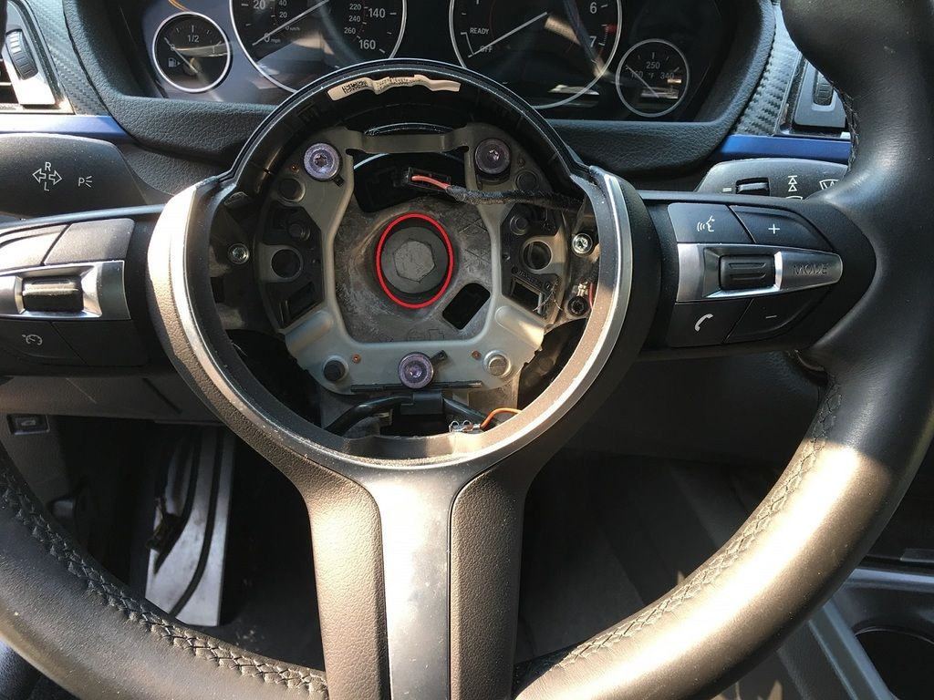 - Remove the 4 6mm bolts from the old cluster as shown below, then remove the wiring connectors and slide the cluster off of the steering column. 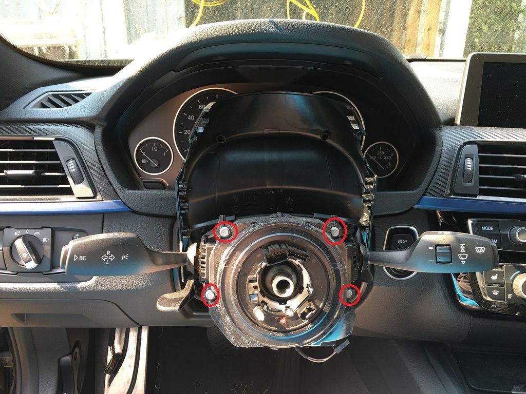 - If you are replacing the cluster, you will need to check to see if you have the Power and Ground wires needed for the Electronics Module. Using the picture below as reference, check to see if you have wires in Pin 9(Power) and Pin 11(Ground) of the black 12-pin connector 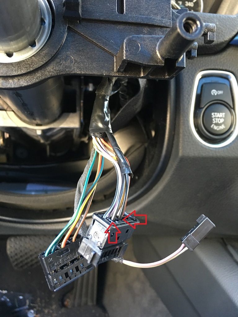 If you have the wires already, you can attach the new Switch Cluster. You will not need to follow the wiring steps below. Adding the wiring(if not already present): - You will need to add two wires to the Steering Column Switch Cluster connector, one which runs to the FEM and one which needs to run to the Rear Power Distribution(Fuse) box in the trunk - Start by taking 2 strands of the 18 gauge wiring and wrapping around 4 feet of it together with the electrical tape - Run that harness through behind/below the radio from the Passenger side to the Driver Side - Using 2 of the Socket Contacts, attach them to the 2 18 gauge wires. Make sure you are able to identify which is Power and which is Ground. I used Red and Black respectively. - After you have attached the socket contacts, connect the Red(Power) wire to Pin Slot #9 and the Black(Ground) wire to Pin Slot #11 of the black 12-pin Steering Column connector - Returning to the Passenger Side of the car, take the other end of the Black(Ground) wire and run it to the FEM - Attach the remaining Socket Contact to the Black(Ground) wire, and then connect it to FEM Connector A173*7B, Pin Slot #10 - Run the remaining wire along the Passenger side of the car to the rear Fuse Box - Using a 10mm socket, remove the hex nut holding the Fuse Box in place - Connect the Double Leaf Spring Contact to the end of the Red(Power) wire - The power wire requires a 10 Amp fuse socket that runs on the KL_15 circuit(Hot during Run). The wiring diagram for the Switch Cluster shows that this wire is supposed to run to the Front Fuse Box in the engine bay, but I did not want to deal with punching a hole in the firewall for one wire, which is why I chose to check the rear Fuse Box - In my car, Fuse F144(10A) was not occupied and is on the KL_15 circuit. In the event that your F144 is occupied, check the next fuse, F143, which is for the convertible top. This should be vacant, unless your car is a convertible. You would just need to replace the 5 Amp fuse with a 10 Amp fuse. - Once you have identified which spot you will use, insert the Power wire into the correct spot and ensure the fuse is in place - Return the Fuse Box to its correct position, and replace the 10mm Hex Nut to secure it into place - If you have not already, you can now return to the Driver’s Side of the car and install the new Switch Cluster - Slide the Steering Wheel back into place. It is grooved with one large tab at the bottom, so you cannot install it incorrectly - Once the wheel is in place, reattach the 16mm bolt to secure the wheel in place - Connect the 2 wire connectors in the steering wheel to their appropriate spots on the Switch Cluster - Reconnect the airbag, then push it into place. You will be able to feel it click back into place and it will be secure - Reconnect the Aerial Transponder and Heated Steering Switch(if present) wire harnesses - At this point, you can replace the Steering Column Trim back into position You should at this point have all of the physical parts for this retrofit installed. Before beginning to code and initialize the system, you must re-install the rear bumper so that the radar units will be initialized properly! After that is done, on to the next challenge: coding! Vehicle Coding: - Reconnect the Negative Battery Terminal to restore power to the car Updating the VO: - In order to properly initialize the FlexRay system, you will need to first update your VO via E-Sys to reflect the Lane Change Warning option (Option 5AG). - Connect to the car via E-Sys. After connecting, the first step will be to add Option 5AG to your FA. Follow the steps in the E-Sys learning guides if you are unfamiliar with how to complete this step. Make sure that you have completed the Write FA/FP option during this process! - Once you have updated your FA with the new option code, you should still not be able to see HC2 in your ECU list, however you will want to go ahead and code all other necessary modules. Activate the FA. At this point, you will need to code at a minimum the FEM, HU_CIC/NBT, ICM, KOMBI, and AHM(if present) modules. Personally, whenever I complete a retrofit, I recode all modules in the car in the event that there is something related to the new retrofit in that module that may have been missed. How you code is up to you, but by coding them all, it avoids the risk of missing something. - Once you have completed this part of the coding, we are done with E-Sys for now and will begin the next step in Rheingold Initializing the FlexRay: - The second step in the coding for the Lane Change Warning is to conduct an initialization of the FlexRay system, since the system will not be looking for the HC2(also shown as SWW in Rheingold), and subsequently you will not be able to see the HC2 module in E-Sys until this is done. - To conduct the initialization, connect to the car via Rheingold, then go to Service Functions -> Body -> Central Gateway Module -> Intialise FlexRay - Follow the on-screen steps in the process to conduct the process. NOTE: You will receive an error stating the Initialization could not be completed. This is to be expected, as the initialization of FlexRay is dependent upon all modules being coded, and since the Lane Change system has not been coded via E-Sys yet, it will cause this error. Don’t Panic!  - You are finished with Rheingold for the moment, and we will be moving on to E-Sys Adding the Coding for the HC2 Master module: - Connect to the car again via E-Sys. After connecting, on the Expert Mode-Coding screen, if you click Read (ECU), you should now see the HC2 listed as one of the modules on your car. - You will now need to create a Cafd file for your new HC2 Module. However, you will need to know your car’s current I-Step Level first - To find this, go to the Expert Mode-VCM Screen. Under I-Steps, click Read. Your current I-Step level will then be displayed, as shown below. Take down this information, and save for future reference if needed. SHOWN FOR ILLUSTRATIVE PURPOSES ONLY: - Now, you can create the Cafd file. On the Expert Mode-Coding screen, highlight the HC2, then click Detect CAF for SWE. When the window shown below comes up, you may have several options available: SHOWN FOR ILLUSTRATIVE PURPOSES ONLY - NOT ACTUAL HC2 MODULE CODING: - You will need to select the option that matches your car’s current I-Step Level. Select the correct option and hit Ok. This should create the Cafd file for the HC2. - Now, VO Code the HC2, since you already completed the VO-coding for the other modules earlier in the process. -OPTIONAL- Some people, myself included, have changed the activation speed of the Lane Change Warning system so that it comes on at a lower speed (17 mph) than originally programmed from the factory. It is not recommended to change it to lower than that value, as some people have reported getting errors. You would need to FA code the ICM for the following option: ICM-3000-C_ZSW_Aktivierunggeschwindigkeit_Funktion_low – change value from 50_kmh to 25_kmh Re-initializing the FlexRay: - Now that the coding has been done for the HC2, we can go back and complete the initialization of the FlexRay system - To conduct the initialization, connect to the car via Rheingold, then go to Service Functions -> Body -> Central Gateway Module -> Intialise FlexRay - Follow the on-screen steps in the process to conduct the process. This time, you should receive a success message to the effect of “Flexray successfully initialized!” Initialization of the Lane Change Radar Units: - While still in Rheingold, we must now conduct the startup initialization for the Lane Change Radar Units(SWW) - To conduct the initialization, go back to Service Functions -> Driver Assistance -> Lane Change Warning -> Initialisation of the SWW sensor system - You will need to follow the on-screen steps to complete the initialization of BOTH the Master and Slave Radar Units. - Once you have completed the steps for both modules, you will need to go back to the Vehicle Test and clear any error/fault messages that have occurred during this coding process. Reassembly of the car: Once you have completed all coding, turn the car off, then back on. Now, go to your Driver Assistance Switch and press the button for the Lane Change Warning. You should see a message on your instrument cluster along the lines of "System available as of 17mph only”, or 35mph if you did not change the activation speed in E-Sys. Assuming everything checks out with no errors, you can re-assemble all of the trim panels/trunk lining, and get ready to test the system on the road. Testing the system: In order to test the system, you will need to spend some time driving around and learning how the system works. In my use and observations, the system is slightly different from others that I have used, in that if you are passing a car at a much faster speed, the system will not light up unless you slow down and the car sits in your blind spot area for a couple of seconds, presumably because it thinks that you will have seen the car you are passing. Additionally, in order to road test the vibration warning and get acclimated to how it feels is to wait until a vehicle is in the warning zone, and turn on your blinker to trigger the vibration warning (just hope you don’t scare the person next to you by making them think that you are changing lanes on them!) Congrats! You now have the Active Blind Spot Detection system to help you know if anything is around you while changing lanes! Last edited by roxxor; 03-18-2016 at 08:38 PM.. |
|
Appreciate
12
|
| 03-18-2016, 01:16 PM | #2 |
|
Lieutenant
 163
Rep 578
Posts |
 The retrofit king is at it again!!!!!!! Thanks so much for taking the time to document this!!! Can't wait to add this to my car!!! Once i get everything ordered, will coordinate on the schedules  You should have taken a video of your blind spot testing...  |
|
Appreciate
0
|
| 04-12-2016, 02:43 AM | #3 |
|
New Member
0
Rep 15
Posts |
You are the best. I recently succeeded surround-view retrofit through your post.
Now, I'm doing lane change retrofit. What does it mean? (Connect 2 contacts together at the wire end and secure using electrical tape or solder. Repeat for the other 2 contacts so that you have 2 cables) Whether is it connecting each 23-27, 24-28 or 23-27x24-28? Why is it need electrical tape? Thank for your answer in advance. Last edited by bemdegari; 04-15-2016 at 02:42 PM.. |
|
Appreciate
0
|
| 04-12-2016, 10:04 AM | #4 | |
|
Major
1140
Rep 1,136
Posts |
Quote:
|
|
|
Appreciate
0
|
| 04-15-2016, 07:41 AM | #6 |
|
Second Lieutenant

89
Rep 258
Posts |
Awesome thread! Would almost make good sense to do this retrofit at the same time as doing a surround view retrofit!
Is it just me, or does anyone else find that the auto dimming mirrors sometimes are a liability in not noticing someone in my blind spot at night time? It's my first experience with side view mirrors with this feature, and obviously I had gotten used to seeing an eyeful of headlight of the car in my blindspot when checking my mirrors before changing lanes at night.
__________________
2017 430ix Gran Coupe
|
|
Appreciate
0
|
| 04-15-2016, 08:51 AM | #7 | |
|
Major
1140
Rep 1,136
Posts |
Quote:
|
|
|
Appreciate
1
fe7565552.50 |
| 04-16-2016, 08:15 AM | #9 |
|
Major
1140
Rep 1,136
Posts |
Maybe one day down the road I will add that, but it seems that some of the parts are extremely difficult to find. To the best of my research, the ACC does not need an FSC Code.
FSC codes are needed for the pedestrian detection and a couple other Driver Assistance Plus features, but those are separate from the ACC. |
|
Appreciate
0
|
| 04-17-2016, 08:51 AM | #10 |
|
Banned


153
Rep 438
Posts
Drives: F30 335i M Sport
Join Date: Dec 2015
Location: Orlando, FL
|
Amazing post. Nice job!
|
|
Appreciate
0
|
| 04-19-2016, 02:28 PM | #11 |
|
Captain
356
Rep 688
Posts
Drives: 22 TR X3MC
Join Date: Aug 2015
Location: New Jersey
|
I already have the blind spot montering in my car. Is there any steps i can skip? What parts would i need since i have the blindspot?
__________________
2022 X3M Comp
2013 335i xDrive (Sold)  |
|
Appreciate
0
|
| 04-20-2016, 12:06 PM | #12 | |
|
Major
1140
Rep 1,136
Posts |
Quote:
 |
|
|
Appreciate
0
|
| 04-20-2016, 12:09 PM | #13 | |
|
Captain
356
Rep 688
Posts
Drives: 22 TR X3MC
Join Date: Aug 2015
Location: New Jersey
|
Quote:
EDIT: Nevermind lol, i read it wrong, the title says lane change warning and i thought it said lane departure
__________________
2022 X3M Comp
2013 335i xDrive (Sold) |
|
|
Appreciate
0
|
| 04-20-2016, 12:19 PM | #14 | |
|
Major
1140
Rep 1,136
Posts |
Quote:
Lane Departure, you would need a different windshield, control switch, camera, camera module, and some FSC codes I believe. |
|
|
Appreciate
0
|
| 05-03-2016, 10:16 PM | #16 |
|
New Member
0
Rep 15
Posts |
I did this retrofit with suitable 3series modules but it was not working properly.
When it was over 20KM, an error message occured like lane change warning error. In ista/d diagnosis, "SWW: programming data faulty -> The SWW control unit has not been programmed" Master & Slave modules are used item. Do you know what the problem is? Last edited by bemdegari; 05-03-2016 at 10:22 PM.. |
|
Appreciate
0
|
| 05-08-2016, 07:48 PM | #18 |
|
New Member
0
Rep 15
Posts |
My slave unit is older than master unit.
Do I have to software update? Did you update HC2 through the esys? or ista/p? Did it work porperly before software update? Last edited by bemdegari; 05-08-2016 at 07:59 PM.. |
|
Appreciate
0
|
| 05-09-2016, 04:55 AM | #20 |
|
New Member
0
Rep 15
Posts |
Did you update only HC2 module?
My I-Step level is F20-14-11-502. I couldn't find same cafd file so I added other cafd file 'F20-14-05-502'. What is the correct I-Step(shipment) when I update via esys? F20-14-11-502 or F20-14-05-502? Last edited by bemdegari; 05-09-2016 at 08:56 AM.. |
|
Appreciate
0
|
Post Reply |
| Bookmarks |
| Tags |
| 5ag, blind spot detection, lane change warning, steelerfan |
| Thread Tools | Search this Thread |
|
|


