Finally got around to writing this up.
I did a fair bit of research using online parts diagrams (real OEM) and Rheingold for the wiring diagrams. The most difficult part is making the wiring harness and extending the existing wiring harness.
Also note if your car already has PDC, the new PMA unit will now control the PDC sensors as well so they will need to be rewired from the REM module to the PMA.
Heres all the parts needed to do it:
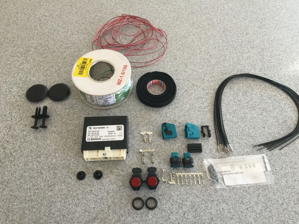 PMA UNIT
1 x 66336864898 Control Module (PMA)
1 x 66336854515 Bracket for PMA (No needed if you have trailer hitch)
2 x 16131176747 plastic nuts to secure PMA holder
2 x 61138364666 PMA connector housing
2 x 61138364662 PMA connector cap (this part doesnt really fit but its as close as I could find, you have to break off a tab on it to secure the plug in)
8 x 61130005197 PMA connector pins (these come crimped onto cables already)
PMA SENSOR
2 x 66209317887 PMA sensors front (part no. is for B50, pick right p/n for your color)
2 x 66206923000 rubber grommet for PMA sensors
2 x 61136925599 Connector housing for PMA sensors
6 x 61138353705 Pin Grommets for PMA sensors
6 x 12527545857 Pins for PMA sensors
WIRING HARDWARE
20-30 metres of 0.5mm cross section wire. Preferably different 3-4 colors for ease of identification (I made do with 2)
1 x 61131378906 Power pin for rear fuse box
1 x 61131387140 Ground pin for rear chassis
TOOLS
Soldering gear
Molex Crimp Tool I used the one I had from making custom PC cables
Knipex Stripper highly recommend one!
Tesco Cloth Tape for OEM look and finish
Sensor Install
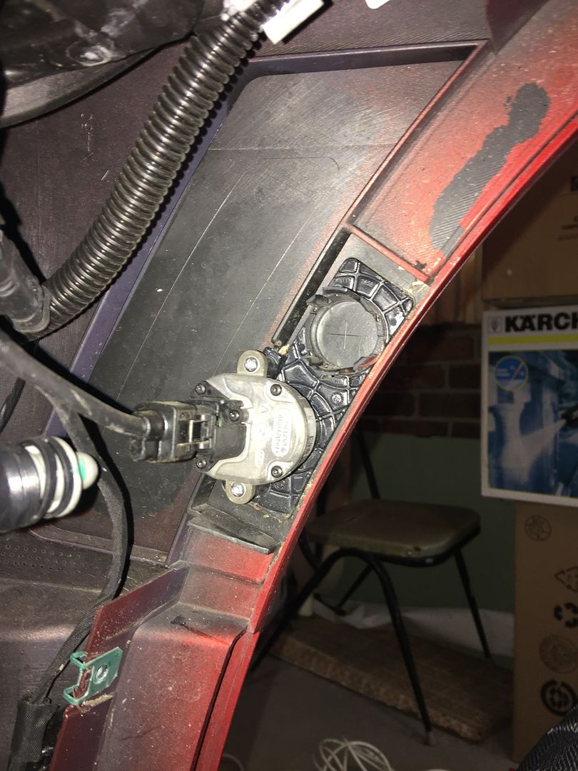
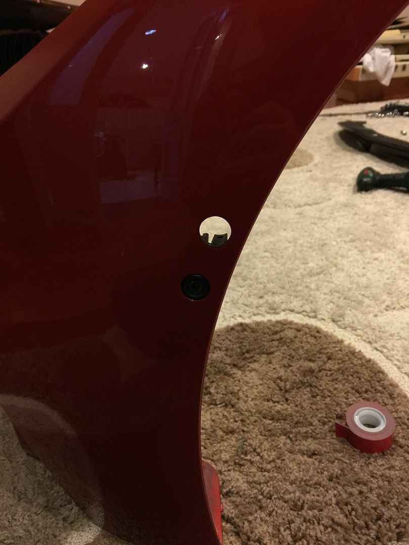
Take your front bumper off (plenty of guides out there). There will be a X marked where you need to drill for the PMA sensor right above the Sideview Camera (if you have it). Drill from the inside out using a 18mm step drill bit. Its very soft plastic so super easy to drill.
Youll need to pull off the existing bracket glued to the bumper to drill the hole, replace adhesive with some 3M VHB tape.
Wiring
Make sure you know which wire corresponds to which pin on the sensor.
Run the wire from the sensor up to the firewall on each side of the car. This is quite tricky in the F8X due to the strut brace which will need to be removed. Follow the path of the cable for the sideview cameras.
Once in the car, route the left sensor wire across the carpet along the front to the right hand side to join the cable from the right sensor. Run this along the carpet under the B billar(sedan) and through to the boot, next to C pillar.
Power
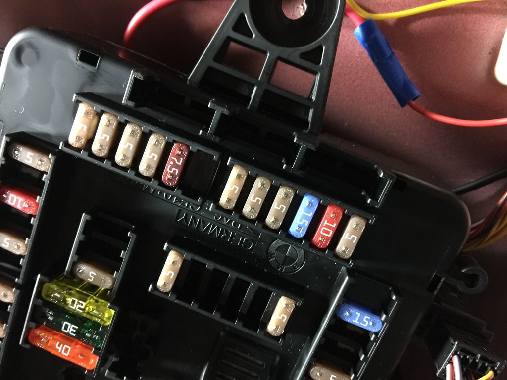
The power for the PMA unit will need to be sourced from the rear fuse box. Connect the power pin to a free slot in the K15 (switched power) block under the fuse box. BMW recommends F146 but mine was used already so I used another one.
Ground
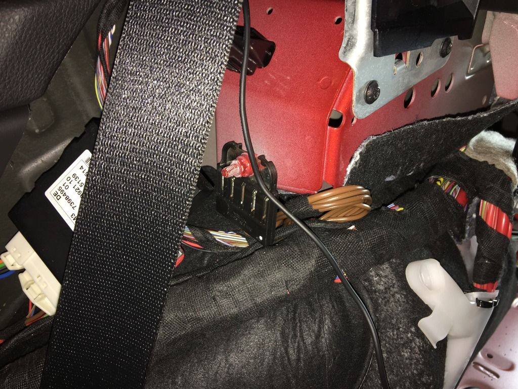
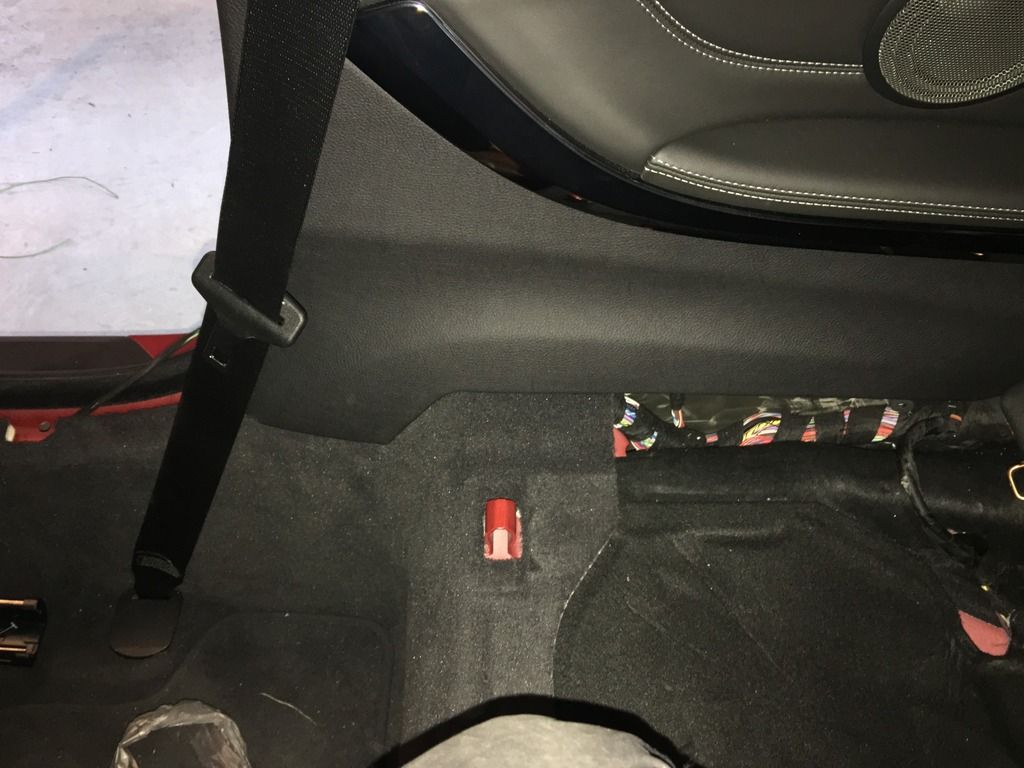
The recommended grounding place for the PMA is the block right under the rear right seatbelt. Connect the pin to a free slot on this block
PMA sensor wires
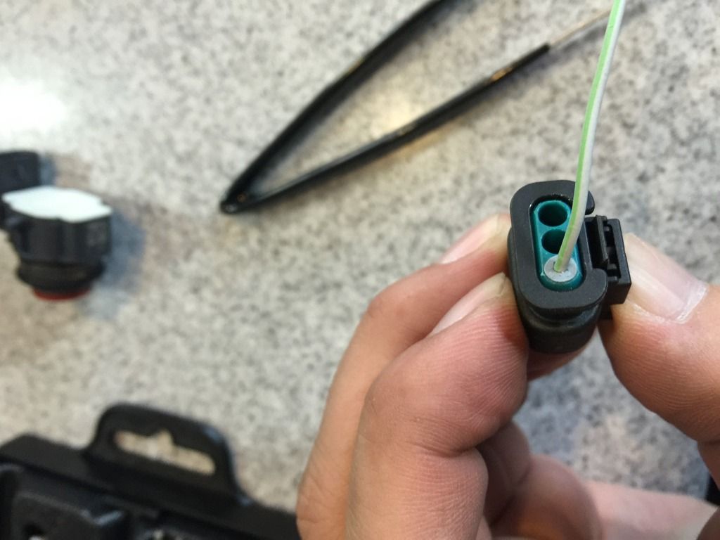
The PMA sensors share a power and ground cable with the front parking sensors. With the clip facing down, the middle wire is the signal wire, left the ground and right is the power. With the 6 cables routed to the back of the car. The 2 power wires join together with the front PDC power wire. The 2 ground wires join together with the front PDC ground wire. And the middle signal wires go into the respective pins on the PMA unit.
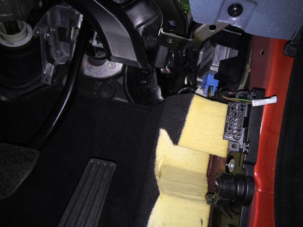
REM unit
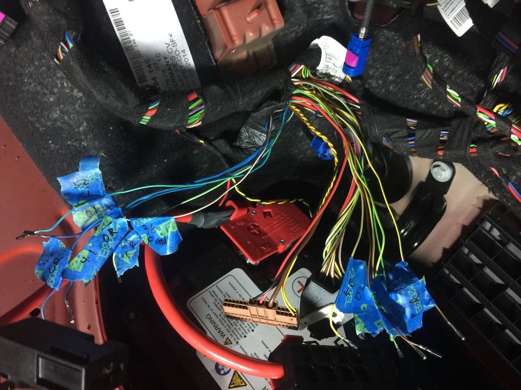
Each signal wire for the existing PDC sensors need to be removed from the REM plug and rewired into the PMA unit. There are 8 in total (4 front and 4 rear). The power and ground for the front and rear sensors also need to be moved (4 in total). So 12 pins need to be extracted!
The connector block with all the pins is in A174*14B this is the longest block of plugs on the REM (brown plug). The pins that need to be removed are:
36 ground
37 ground
38 rear centre right (needs to be extended to reach the PMA unit)
39 rear outer right (needs to be extended to reach the PMA unit)
40 front centre right
41 front outer right
48 power front sensors
49 power rear sensors
50 rear outer left (needs to be extended to reach the PMA unit)
51 rear centre left (needs to be extended to reach the PMA unit)
52 front centre left
53 front outer left
2 wires need to be added to connect the REM to the PMA unit. These are the K-CAN wires and ideally, they should be a twisted pair. They go into pins 29 and 44 on the same REM plug.
PMA unit
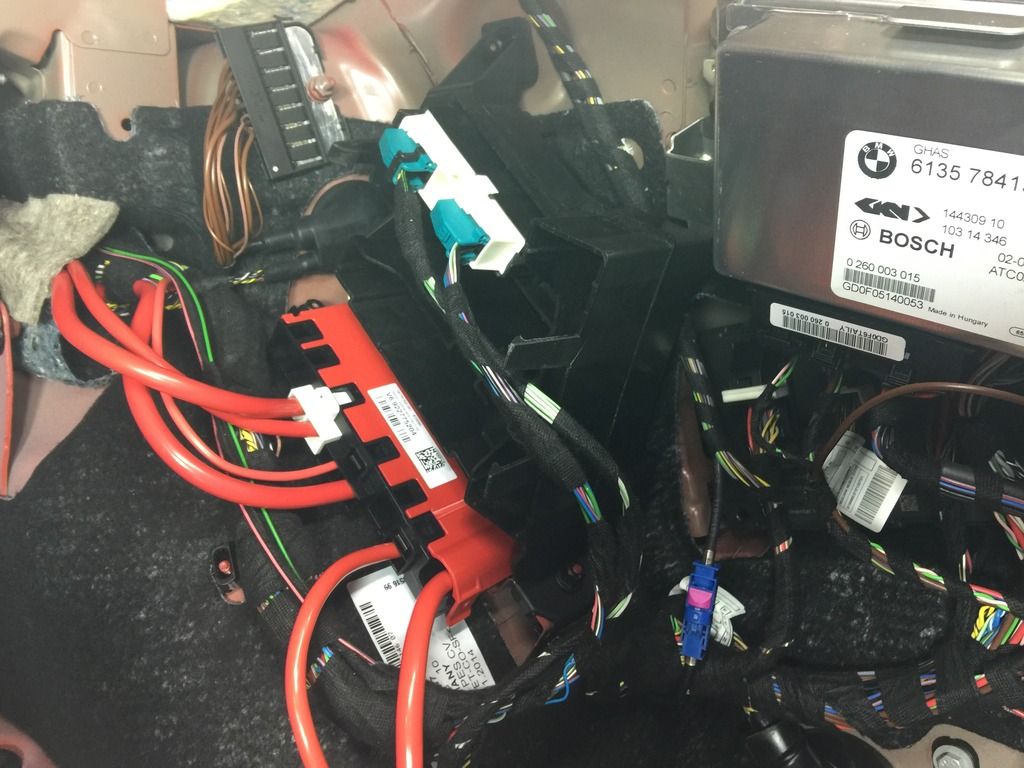
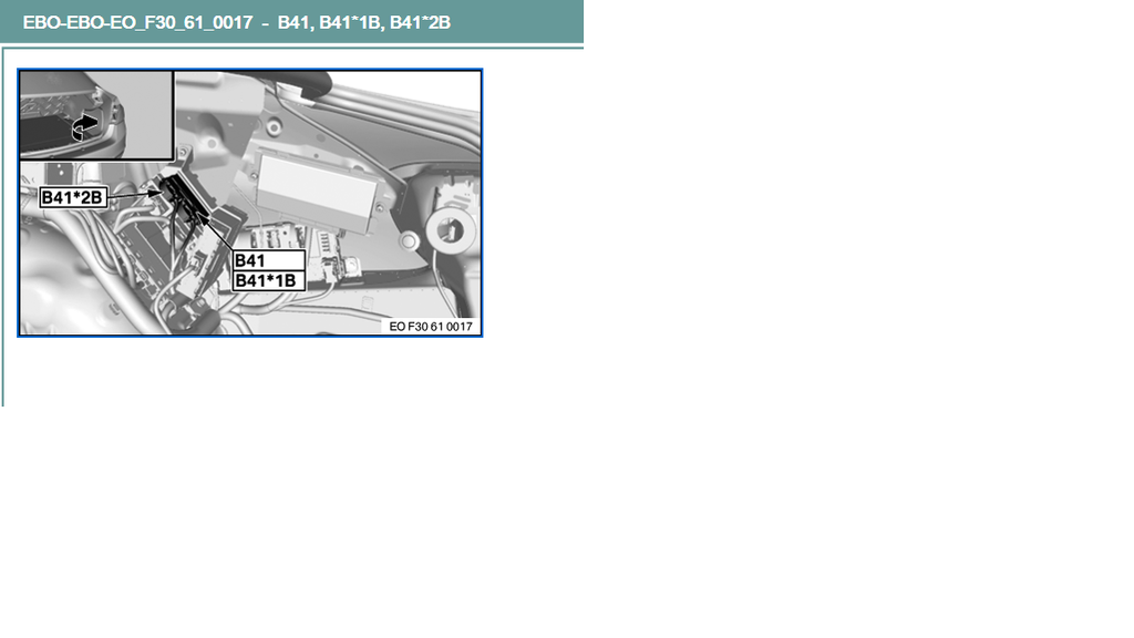
There are 2 plugs that go into this unit, 2B and 1B. Refer to the picture to see which one. Basically if the wires point towards the right, 2B is left connector and 1B is the right connector.
1B:
2 36 from REM
3 48 from REM
4 Power from rear fuse box
10 PMA sensor right
11 PMA sensor left
12 52 from REM
13 40 from REM
14 41 from REM
15 53 from REM
2B:
2 49 from REM
5 37 from REM
11 connect to 29 on REM
12 connect to 44 on REM
13 39 from REM
14 38 from REM
15 51 from REM
16 50 from REM
Programming
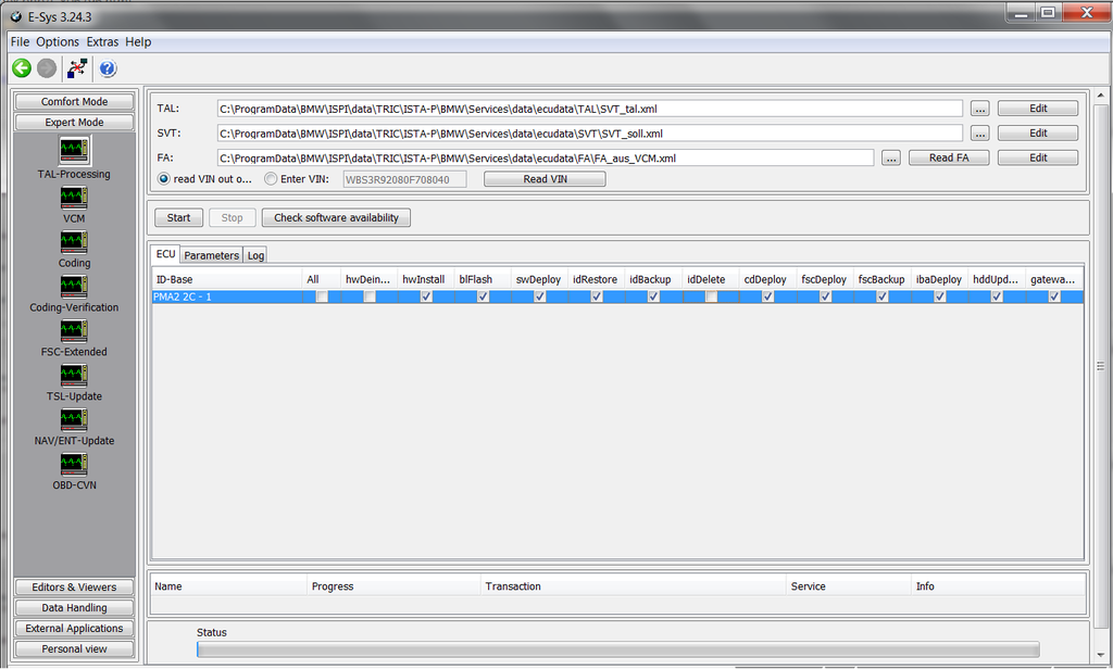
If you have a new PMA control unit, you will need to program the module with the version of psdzdata you have. This is done the same way as you would if you were upgrading your ECU modules with the latest psdzdata. TAL-processing.
Coding
Lastly, you need to add 5DP to your VO and VO code the following modules:
EPS
EGS (not needed on DCT cars)
DSC
FEM
ICM
KOMBI
HU-NBT
REM
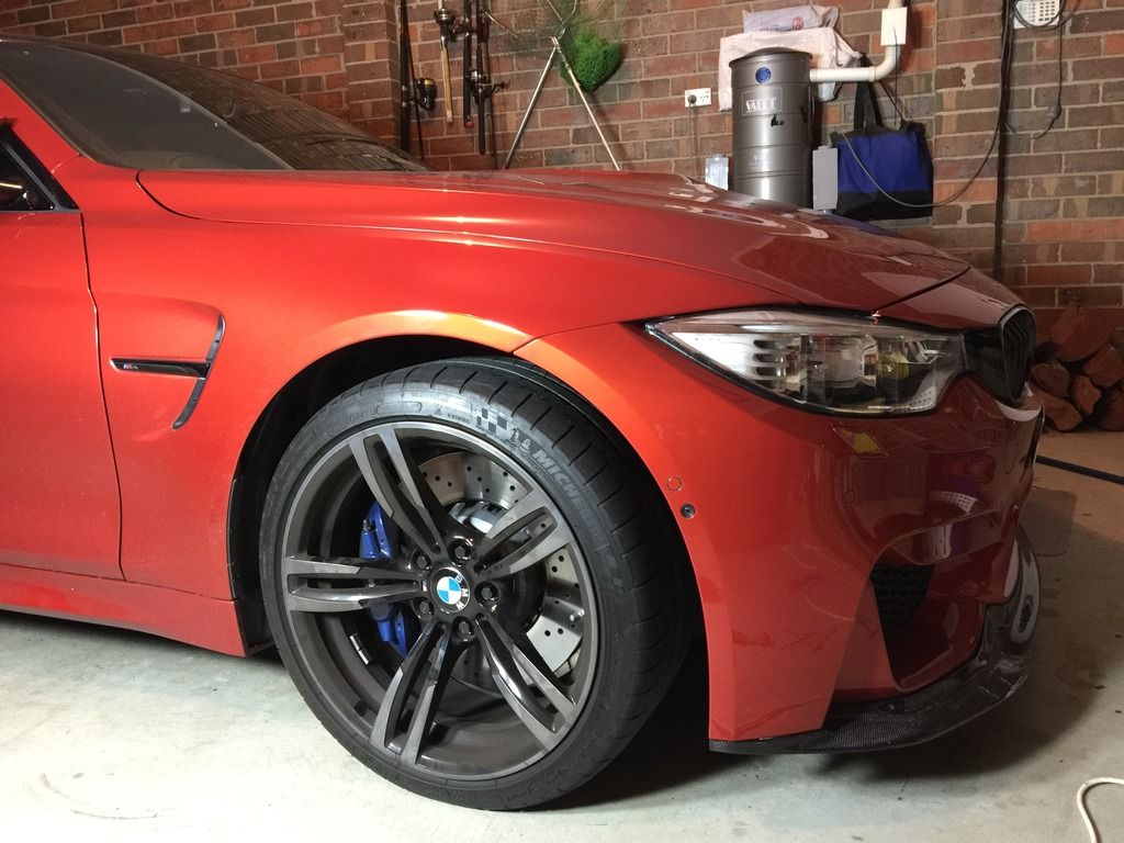
And youre done! When I first tested this, I realised Id wired some sensors wrong. Just make sure you connect to the right pins and all should work.
Next up is to see if its possible to install 2 additional rear PMA sensors to make perpendicular parking work (like on the F30LCI). The pins are already available on the PMA control unit 17&18.