After months of patience waiting for all my parts to arrive, I have finally completed my PDC retrofit and am doing a writeup of the Rear PDC retrofit. This can be done by itself or with the Front PDC(which has a detailed writeup
here). I decided to locate and order the parts myself rather than ordering from a vendor as I already have the stuff to do the coding myself, and figured it would save a little bit of money. If you are interested in sourcing the parts yourself, feel free to PM me for details.
NOTE: Like any DIY project, proceed at your own risk. I am not responsible for anything that happens to your vehicle as a result of attempting this retrofit. This information is simply posted as a reference to help others who may wish to do this project on their own. With that said, onto the writeup!
Parts List:
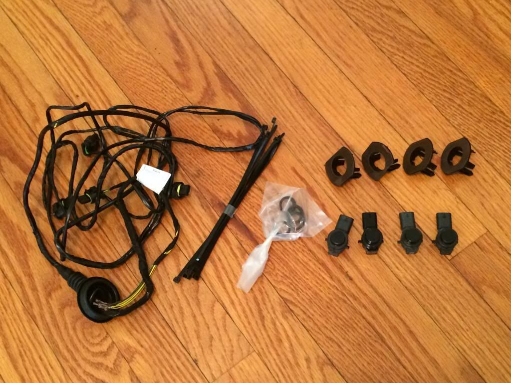
- Sensors (4x) - For my car(Black Sapphire Metallic), the pre-painted sensor part number is 66209261582. Different paint codes will have different part numbers, you can find yours on RealOEM
here. However, contrary to popular belief, you can gently sand the color off of a sensor and lightly repaint over it using touch-up paint with no negative effects as to sensitivity, which is what I did for 3 of my 4 rear sensors. More on this in the prep-work section. Total paid for 4 sensors w/ shipping - $170.20
- Rear PDC Install Kit - Part #66202339614 - This kit includes the retrofit cable, cable zip ties, and 4 rubber Decoupling Rings which fit around the sensors when they are placed in the bumper. Total paid for kit w/ shipping - $126.86
- Rear Bumper Mounts (Set of 4) - Part #51128059970 - Unlike the mounts for the front bumper, these are the same regardless of if you have an M-Sport bumper or not. These are what attach to the bumper via adhesive and hold the sensors in place. Total paid for mount set w/ shipping - $20.36
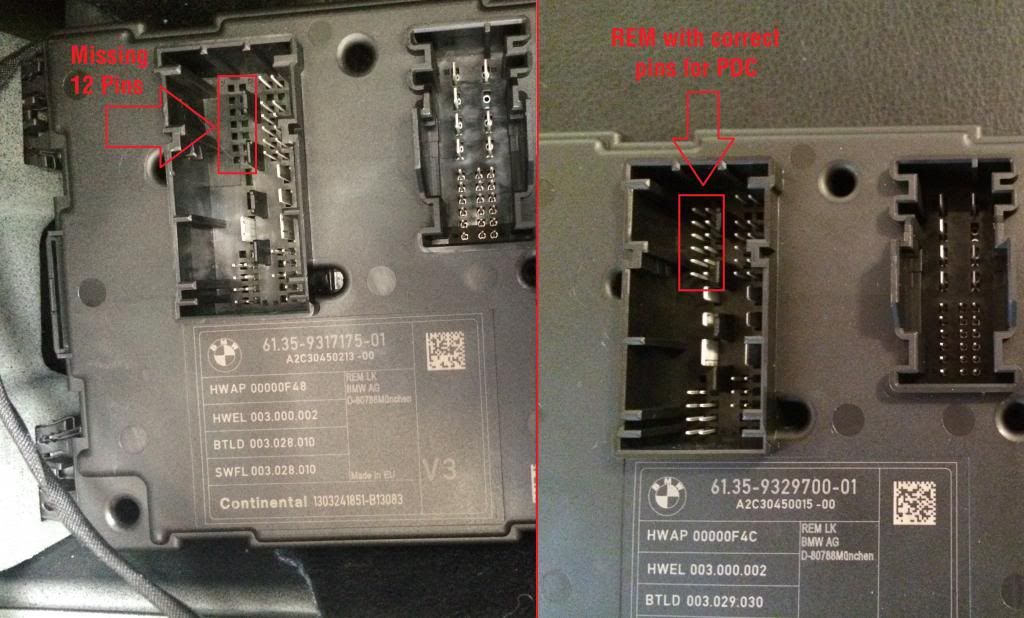
- Rear Electronics Module (REM - This is the module located above the battery in the right side of the trunk - see pictures for reference to identify it) - Please read the Prep Work section before ordering this part!!!! - Part #61359329700 - Depending on which REM you have in your car, you may need to replace this in order to have the correct pin connections for the PDC sensors. This particular part number has the correct pins for all option codes, therefore I found it easier to order this new rather than to search for a module that matched the pins I had, plus the added pins for the PDC. Total paid for REM w/ shipping - $207.68
OPTIONAL - Extra wire connectors(Bushing Contact) - Part #61130005201 - I ordered this out of necessity as I managed to break one of the pins as I was pushing them into the REM socket. These can be flimsy under the amount of pressure needed to push them into the connectors, and since they are around $1.80 each, I recommend picking up a couple just to be prepared in the event you need them.
Total spent on parts including shipping - $525.10
Tools List:
- 8mm socket
- 10mm socket
- Torx set - At a minimum you will need a T20 bit
- Masking Tape
- Rubbing Alcohol
- 18mm Drill Bit - You can use a regular bit or a step drill bit, which is what I used
- Smaller size drill bit - no particular size, just to be used to drill your guide hole in the bumper
- X-Acto knife or deburring tool
- Small Flat Head Screwdriver
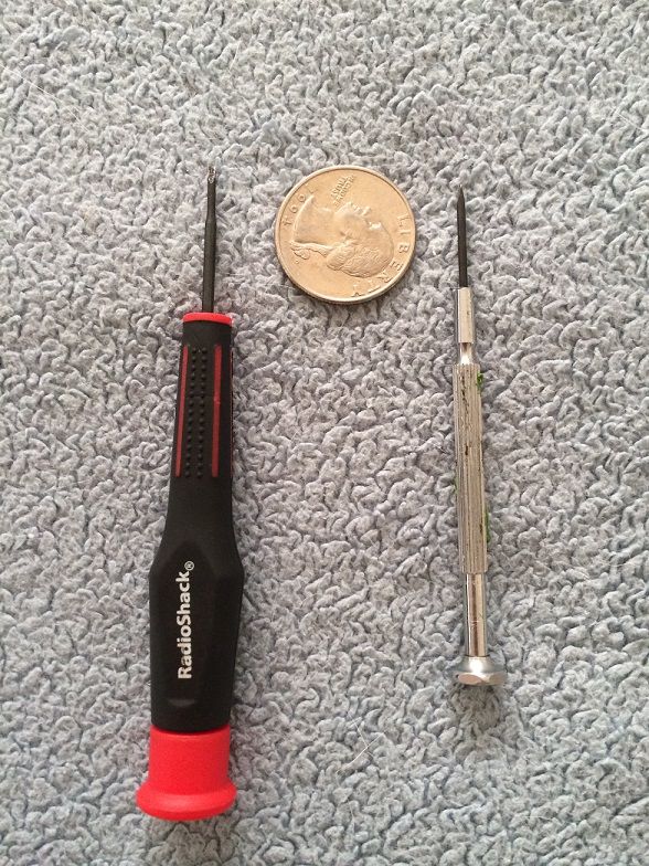
- Mini Flat Head Screwdriver - I used this to help with pushing the pin contacts into the REM socket. Picture shown below with a quarter for size illustration
 Prep Work:
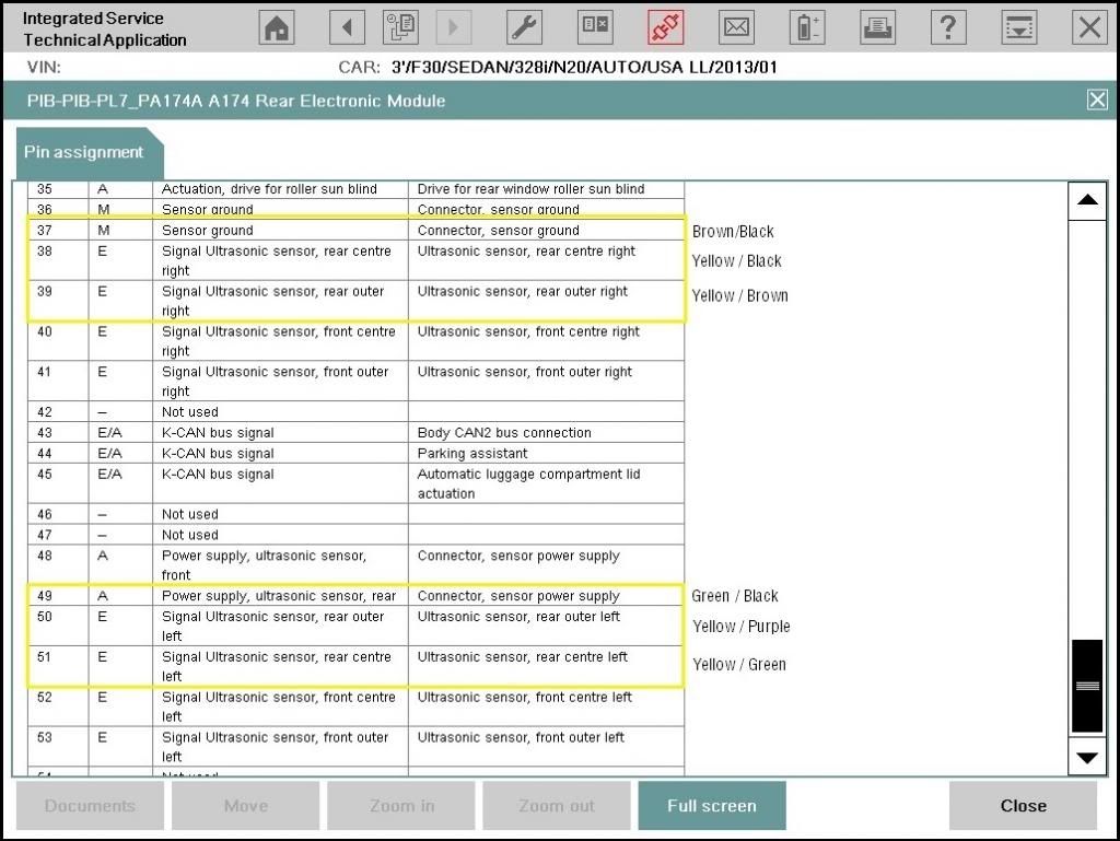
- The first thing you will want to do before ordering parts for this retrofit is to check your REM module to see if you already have the correct pins for the PDC sensors. Remove the far left connector, and use the picture below as a reference guide. If you do not have the pins in the highlighted box, you will need to replace the REM.
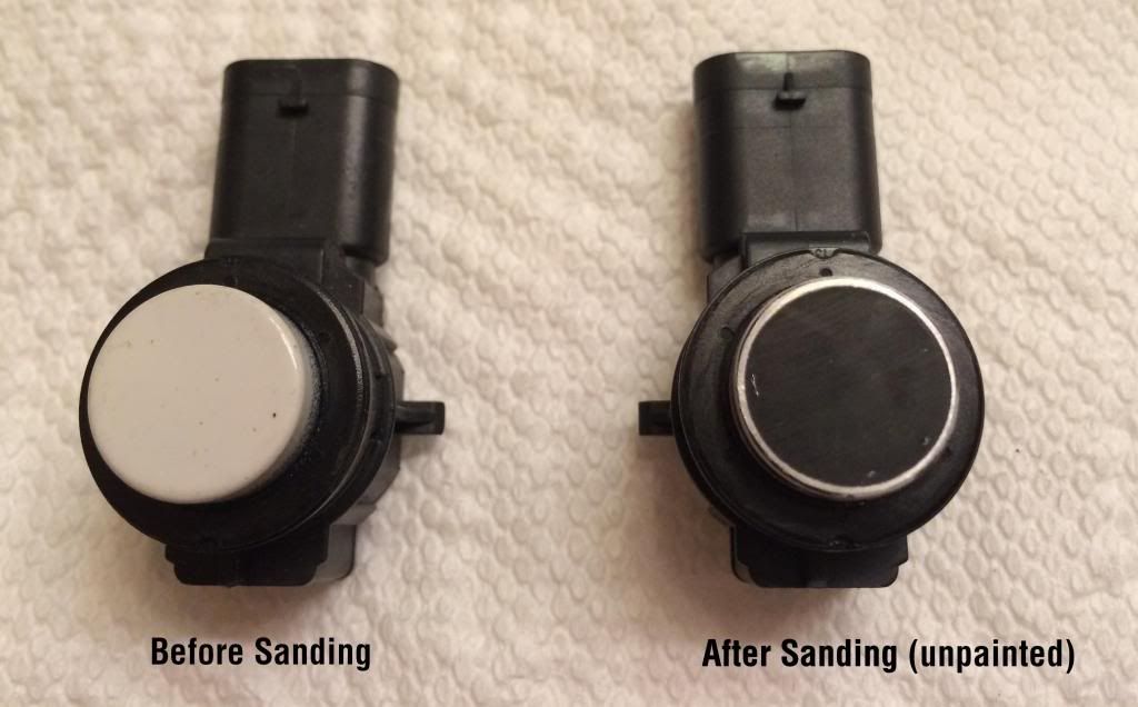
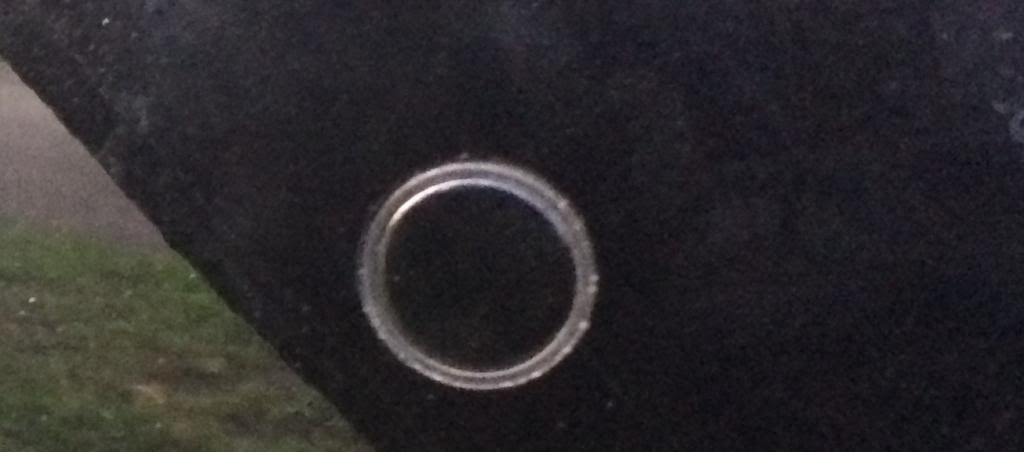
- PDC Sensors - Despite the back and forth on the forums and the internet, I found that while it is not usually recommended, it is possible to gently sand down a pre-painted PDC sensor and lightly repaint it with the correct color code with no issues with sensitivity or distance. This can be helpful in ordering used sensors or ordering black sensors(which are cheaper) and repainting them yourself. In doing this retrofit, I found 3 sensors which were painted white, and gently used fine 400 grit sandpaper to clean off the white paint as best I could from the top and the sides. Then, I used touch-up paint matching the color of my car (Black Sapphire Metallic), and using the included brush, lightly painted a coat of color over the sensor. After letting it dry(30 min - 1 hr) I checked for any unevenness, and if needed, lightly touched up any spots. In the pictures below, you will see the sensor after you remove the paint, and what one of the re-painted sensors looks like on my car. I have tested these using flexible yet stationary objects(hedges, plastic bins) and they are just as sensitive as the factory painted sensors. If you choose to go this route, please make sure you do similar tests with yours after you paint them to make sure they work properly and are correctly measuring distance from objects.
 Beginning the Retrofit:
- Disconnect the negative(black) terminal of the battery(10mm bolt)!!
Remove the Rear Bumper:
- In order to make this easier, I removed my taillights during the process. To do this, simply use the small flat head screwdriver to remove the twist locks holding the rubber cover over the bolts, then remove the 2 10mm bolts and gently pull the taillight out, disconnecting the plug before setting them off to the side.
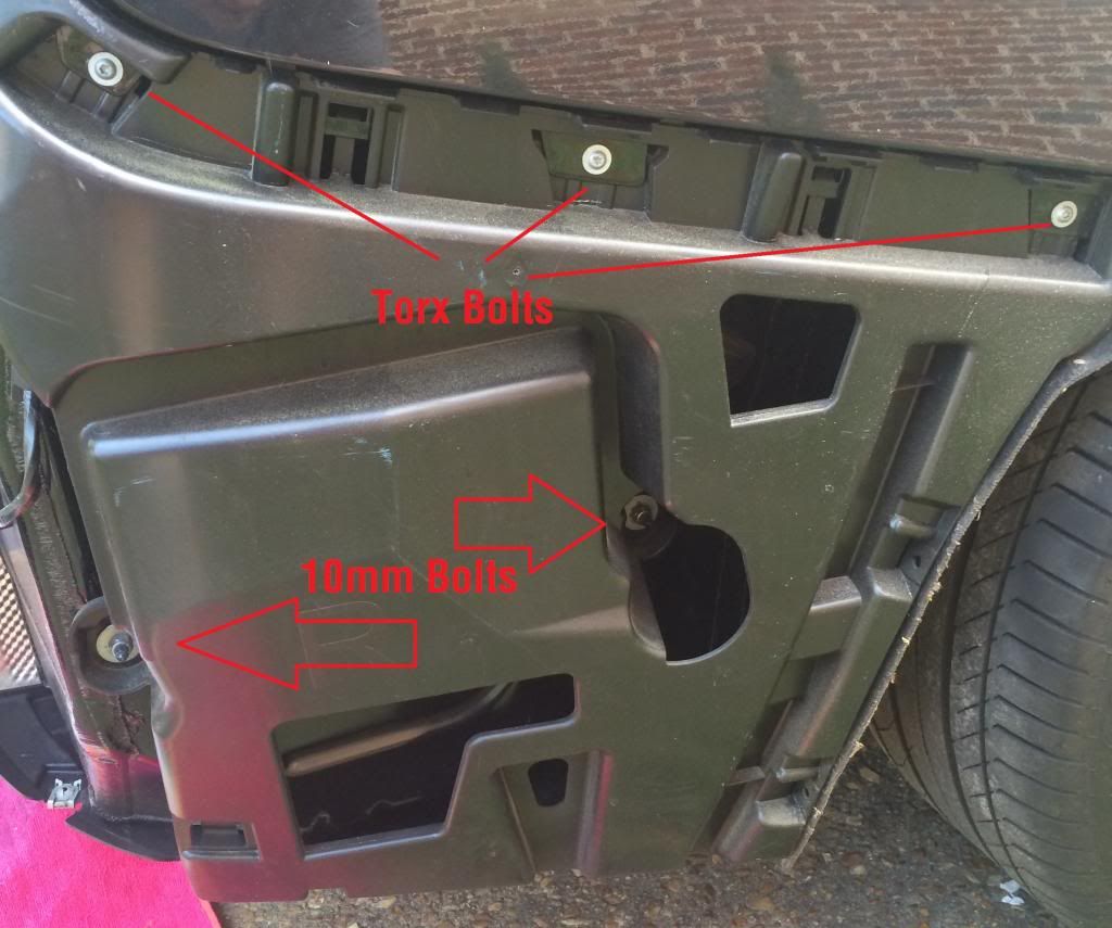
- Next, remove the two 10mm bolts(one on each side) near the top center of the bumper.
- Now you will need to remove the bolts from the underside of the bumper. There are 3 Torx screws in the center area of the bumper, and 4 8mm bolts on each side of the bumper.
- There are 2 8mm bolts and 1 Torx screw holding the bumper to the lining in each wheel well that will need to be removed.
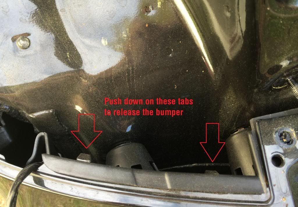
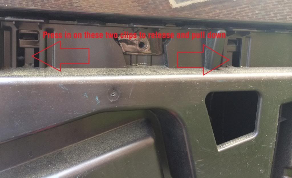
- After removing all the bolts/screws, you will need to press down on the tabs on each side of the top of the bumper(driver's side shown in picture below), then gently pull out on the left and the right of the bumper on the side of the car, and it should come off with ease. I put a thick blanket down underneath the bumper just so that it would not scratch when sitting on the ground.
 Drilling/Installing the Sensors to the Bumper:
- I cannot speak for each trim lines bumper, however the M-Sport bumpers on my car came with the PDC Sensor drill points pre-marked which was a great help. If you do not have the pre-marked spots like the ones shown below, you can visit a dealership and take pictures to get a general idea or look up bumpers with the pdc holes on the internet for reference.
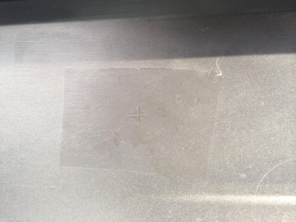
- Place a piece of masking tape on the painted side of the bumper. This will help to keep from pulling off excess paint as the drill is going through the bumper.
- Using the smaller size drill bit, drill your guide hole at the very center of the plus sign marking on the bumper, going all the way through the bumper. REMEMBER: slow and steady wins the race here!!
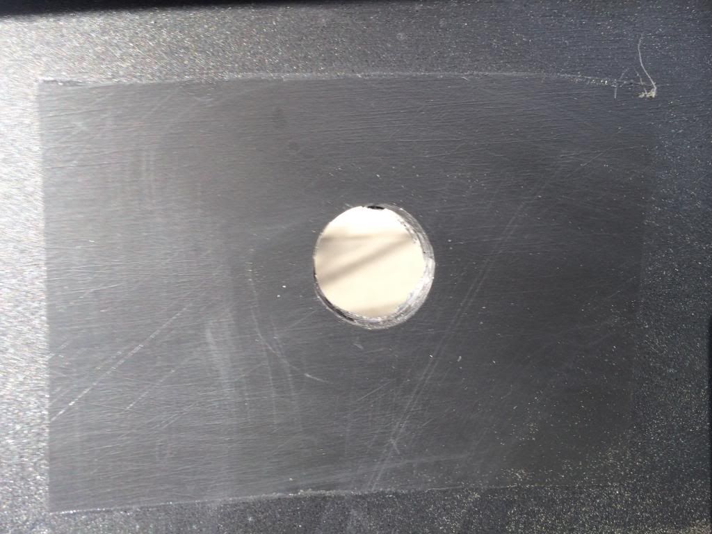
- After you have your guide hole, you can use the 18mm drill bit to drill the hole through the bumper. You may want to stop half way through just to remove some of the excess material that will build up from the drilling.
- Once you have drilled the hole, remove the masking tape from the painted side. Very carefully run the deburring tool(or X-Acto knife if you don't have a deburring tool) around the edge of the hole on the painted side to remove any leftover paint pieces from the hole. You can see the paint pieces/"flaps" that I mentioned around the top and bottom of the hole in the picture below
- Once you have finished clearing away any leftover paint/material from the edge, use the rubbing alcohol on both sides of the bumper where you drilled to clear away any residue from the tape and to clean the backside where you will be attaching the mount for the sensors.
- Place 1 Decoupling Ring around the top of the sensor, and place the sensor inside the mount. Once you have done this with all 4 sensors, test fit them to the holes with the backing still on the adhesive to make sure that they fit properly into the holes you drilled.
Note: When installing the sensors, the end with the connector socket should be facing away from the center of the bumper.
- Once you have done a test fit to ensure the sensors fit properly in the holes, remove the adhesive from the mount and place the sensor in the hole, pressing firmly on the back of the mount for about 10-15 seconds. Make sure you press down on all areas of the mount to make sure you get good adhesion to the bumper. Repeat for the other 3 sensors, and you are done with installing the sensors!
Running the wiring:
- In order to get access to the wiring harness already running into the trunk, you will need to remove the plastic panel on the right side of the car where you removed the bumper, as shown here. Remove the 3 Torx bolts and 2 10mm Bolts.
- Next, press in on the two tabs holding the piece in place, and gently pull down to remove the panel
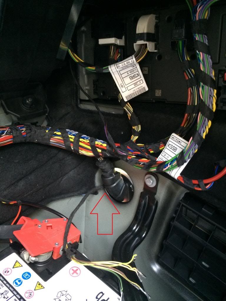
- Once you remove the panel, you will be able to see the connector that passes the wiring through to the inside of the trunk. Towards the outer edge(away from the center where the wires run) you can use the drill or X-acto knife to make a small hole to run the wiring for the sensors through. You can then use some silicon sealant on the outside of the area you made the hole through to ensure no water gets into the trunk compartment. I would not recommend doing what I did and pulling the rubber stopper out, as it was extremely tough getting it back into the hole.
 Replacing the REM:
**If you are replacing your REM, follow these steps. If you do not need to replace the REM, skip ahead to "Connecting the Wiring"**
- To remove your existing REM, disconnect the 3 wiring bundles that are connected to the REM by pressing down on the tab and sliding the "handle" back. The harnesses should then slide right out.
- Next, remove the 10mm bolt that is holding the REM to the car. Be careful in this step not to let the bolt fall down into the battery well.
- Once the bolt is removed, you can slide the REM down to rest on the battery in order to remove the last connection. Using the small screwdriver, remove the red tab that is holding the red battery cable socket in place. Then, you can press down on the tab and pull the cable out of the REM.
- To install your new REM, simply re-connect the red battery cable, place the new REM in place in the trunk, replace the 10mm bolt, and then reconnect the two right wiring harnesses. Leave the far left one out, as you will need it out in order to connect the PDC wires.
Connecting the Wiring:
- In order to be able to add the PDC wiring pins into the far left socket of the REM (Connector A174*14B), you will need to gently pull on the sides of the black connector which holds the brown and blue connectors into the harness, then slide both of them out of the harness.
- For the PDC wiring, we will only be working with the brown harness, as seen in the picture below:
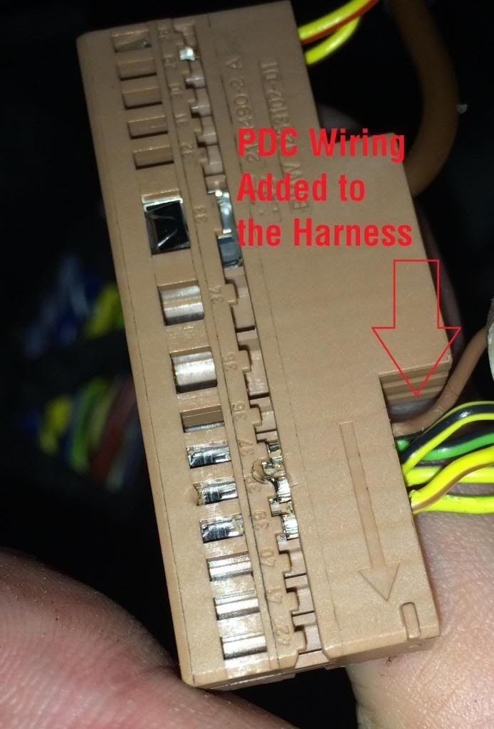
Here is the list of which pins to place in the appropriate numbered slot:
Pin 37 - Ground Wire - Connect the Brown/Black wire
Pin 38 - Inner Right Sensor - Connect the Yellow/Black wire
Pin 39 - Outer Right Sensor - Connect the Yellow/Brown wire
Pin 49 - Power Wire - Connect the Green/Black wire
Pin 50 - Outer Left Sensor - Connect the Yellow/Purple wire
Pin 51 - Inner Left Sensor - Connect the Yellow/Green wire
I have also included the REM wiring chart from ISTA/D as well:
Remember, when pushing these pins into the sockets, be very careful as they are not the strongest in the world, and can easily break. I recommend using the end of the mini-screwdriver to push the pin into the socket.
- Once you have completed adding the wires to the harness, place both the brown and blue harnesses back inside the larger black connector, making sure they lock into place. Then, replace the connector back into the far left socket of the REM.
Finishing up the physical installation portion:
- Before you reinstall the bumper, you will need to replace the plastic panel removed to gain access to the wiring on the right side of the car. Simply lift it up until the tabs click into place, then replace the 2 10mm bolts and the 3 Torx screws. Be careful to make sure you run your wiring harness out the back side of this panel so you are able to connect it to the sensors on the bumper.
- Now you should be ready to replace your rear bumper. Connect the far end of the wiring harness to the far left sensor, and then repeat for the remaining 3 sensors. Once you have connected all 4 sensors, carefully lift the bumper back up into place and push in the tabs along the top and the side. When you have aligned the bumper, begin replacing the bolts and screws until you have completed re-attaching the bumper.
- Reinstall your taillights, making sure you reconnect them to the plugs that you removed when you took them out. Replace the 2 10mm bolts on each headlight, then replace the rubber cover and re-attach the twist cap that holds it in place.
- Finally, reconnect the negative battery terminal, and replace the cover to the battery well.
Coding:
I will add more info on the coding in a day or two, I will go back through the steps and make detailed notes. Basically, if you did not replace the REM, all you will be doing is adding the VO code for the new option:
Rear PDC Only: Option 507
Front and Rear PDC: Option 508
If you had to replace your REM, you will need to create a new Cafd file for the REM(if it is brand new). Once you have done that, or if it is a used module, you will just VO code it to match what you have on your car. Again, it isn't as complex as it sounds, I will write out more details later.
Testing:
- After you have finished the coding, the obvious sign that your install was successful is that when you put the car in reverse, the PDC screen will appear on your iDrive screen.
- Assuming success in the step above, you will want to test your sensors before you start backing up towards solid objects(i.e. buildings, other cars, etc.) by placing some relatively soft objects(see my examples mentioned above in the Prep Work section) that you can slowly back up towards and that won't damage your bumper should you back up too far. Use this as a learning period as well, where once the on-screen display shows red and the tone is steady, you get out of the car and look at how much room is left between your car and the object so you get a feel for distance when you are backing.
- You can adjust the volume level of the PDC alert under Settings - Tone - Volume - PDC. Note that this option won't appear until after you have completed the coding steps above.
And that should be it, time to enjoy your new parking sensors!! If you have any questions, please feel free to ask!
