

BMW 3-Series and 4-Series Forum (F30 / F32) | F30POST
>
DIY: F30 Surround view retrofit

| 11-24-2015, 02:57 AM | #23 |
|
Private First Class
 
32
Rep 144
Posts |
Thank you for DIY. Today just picked up car from dealer. I bought all parts from your list and dealer just installed it. BMW sent new software for my car that include this option. So I not need to code my car.
My notice: If you have rear camera, you not need to buy 66539232797 Bracket, control unit 07149158182 Fillister head screw with collar Also you can buy tool to make perfect hole in bumper. It is VAG and has part number: BEA 000001. Cost just 20$ |
|
Appreciate
1
Bimmer_pnoy16.50 |
| 11-24-2015, 11:28 AM | #24 |
|
Enlisted Member
 31
Rep 42
Posts |
Thank you for your feedback!
You are right, some parts are not needed. I have also retrofitted the rear view camera and forgot to mention it in the post. I'll update the DIY. |
|
Appreciate
0
|
| 11-24-2015, 12:48 PM | #25 | |
|
Major
 1151
Rep 1,148
Posts |
Quote:
Are you by chance able to take a picture of the part of the door harness that connects to the mirror? I might be able to figure out the cable by looking at that, as I assume that it is similar to 61129281712, just longer to reach from the mirror connector to the door connection. Also, in the picture of the wiring bundle, there are 2 silver connectors that do not have a cap. Are those the connections that go from inside the car to the door connector for the top down mirrors(that you had to use the female adapter to pull into place)? Last edited by roxxor; 11-24-2015 at 01:19 PM.. |
|
|
Appreciate
0
|
| 11-24-2015, 01:55 PM | #26 | ||
|
Enlisted Member
31
Rep 42
Posts |
Quote:
This is the cable that I've bought (1m and 3m): http://www.ebay.com/itm/Pigtail-cabl...item2579d47753 I've removed plastic cap and tried to connect the mirror with the body. The mirror part was OK, but I had some problems with the door-to-body connector. If you take a deeper look at the picture below, you'll see that it's an L-shape connector and the cable I bought has a straight connector. Maybe I could drill a bigger hole in the connector and route it through, but I wanted to make the retrofit as OEM as possible so I decided to buy the original wiring harness.  If you really cannot find the door harness, maybe you could contact the eBay seller and ask them to make a custom cable for you that will have one side as the cable mentioned above and the other side something like this: http://www.ebay.com/itm/Fakra-Z-crim...wAAOSwq7JT6b-P Quote:
Last edited by hrvojehk; 11-24-2015 at 02:24 PM.. |
||
|
Appreciate
0
|
| 11-24-2015, 02:10 PM | #27 | |
|
Major
1151
Rep 1,148
Posts |
Quote:
|
|
|
Appreciate
0
|
| 11-24-2015, 02:21 PM | #28 | |
|
Enlisted Member
31
Rep 42
Posts |
Quote:
|
|
|
Appreciate
0
|
| 12-16-2015, 06:03 PM | #30 | |
|
Major
1151
Rep 1,148
Posts |
Quote:
|
|
|
Appreciate
1
|
| 12-23-2015, 07:23 PM | #31 |
|
New Member
12
Rep 11
Posts |
Does anyone know if there is any practical difference between the side and top view cameras? They're different part numbers and obviously get installed in different places, but from pictures they look identical. Is there an actual physical difference or different lenses that give different viewing angles, or are they really the same thing with different part numbers?
|
|
Appreciate
0
|
| 12-28-2015, 05:21 AM | #33 | |
|
Lieutenant
 163
Rep 578
Posts |
Quote:
You mentioned above, you bought a 1M & 3M (i understand you later realized you needed a right angle connector) but why did you order a 1M & a 3M? Were you not sure a 1M would be long enough to reach from the mirror to the door harness connector so you bought a 3M as well??? So which length was correct if we try to have that seller on ebay make a cable with the straight end on one side & L connector on the other? Here is what i have been able to find on the door harness... I think the new part # EUR version of the Driver side door with all options (i.e. Comfort access, auto dip, electric seat adjuster, light package and surround view) = 61129259985. The passenger door with those same options would be = 61129313649. Any reason we couldn't use the EU cable in US cars??? Real OEM Europe door wiring harness hrvojehk, why did you order 61129259975 over say 61129259985? Do you not have comfort access, memory mirror seat??? I notice on 61129259975 the options are "or" and not "and"? The best I can find on the US part # still doesn't seem like it has all the options my car has. The passenger door does, but not the driver side door. I feel fairly confident the US passenger door for my car would be 61129313649 for Comfort access "and" auto dip "and" electric seat adjuster "and" light package "and" surround view... However the driver side door is the issue... 61129259991 it's missing options like "Comfort access & Light package". So that is why i am confused:  Real OEM US door wiring harness |
|
|
Appreciate
0
|
| 12-28-2015, 05:41 AM | #34 | |
|
Lieutenant
163
Rep 578
Posts |
Quote:
|
|
|
Appreciate
0
|
| 12-28-2015, 09:13 AM | #35 | |||||
|
Enlisted Member
31
Rep 42
Posts |
Quote:
If you decide to order the cable from the seller on eBay, make sure you send him the correct pin number connections! The cable I've bought didn't have correct pin mapping. I think BMW uses pin connections 1-4, 2-3, 3-2, 4-1 and the cable had 1-2, 2-1, 3-4, 4-3. For more details regarding pin numbers, please use Rheingold. Quote:
Quote:
Quote:
My car is equipped with Comfort access, auto dip, light package (and now Surround view  Quote:
If I were you, I'd call and ask my local dealer what's the difference between the EUR and US harnesses. |
|||||
|
Appreciate
0
|
| 12-28-2015, 09:28 AM | #36 | |
|
Enlisted Member
31
Rep 42
Posts |
Quote:
I think you can buy the jumper wire in every electronic store or from eBay. For example: http://www.ebay.com/itm/40ps-Dupont-...-/272057318211 Last edited by hrvojehk; 12-28-2015 at 09:46 AM.. |
|
|
Appreciate
0
|
| 01-06-2016, 09:27 AM | #37 | |
|
Lieutenant
163
Rep 578
Posts |
Quote:
|
|
|
Appreciate
0
|
| 01-06-2016, 01:01 PM | #38 | |
|
Major
1151
Rep 1,148
Posts |
Quote:
|
|
|
Appreciate
0
|
| 01-09-2016, 03:44 PM | #39 |
|
Major
1151
Rep 1,148
Posts |
So, I finished up this retrofit a couple weeks ago, and figured I would post a small write-up since I did a couple things differently than Hrvojehk. Firstly though, a huge shout out to Hrvojehk for leading the way in posting the information for this retrofit!!
Total cost for this ended up being around $1000 USD, not factoring the extra money from selling the original Rear View only Camera Module and center console switch. Patience and waiting for finding good deals on the auction sites makes it much more reasonable than buying parts new, however some you just have to, like screws, cable sets, etc. DISCLAIMER: As with all DIY projects, undertake this at your own risk. I am not responsible for anything that happens to you or your car! With that said, on to the write-up! Pre-Requisites: In order to successfully add this to your vehicle, you will, at a minimum, need to have Front and Rear Park Distance Control (Option 508). Factory or retrofitted does not matter. My write-up is written under the assumption that the vehicle already has the Rear View Camera (Option 3AG). If you do not, you will need to obtain extra parts not listed below. Parts List: These are the additional parts I ordered/used, and vary from the original post since I did not replace the entire side mirrors, and I did not replace the entire door wiring. Additionally, since I already had a small HSD wire from my Rear View Camera Retrofit, I was able to splice it to the new one, so I did not need to order the rear view repair cable. I also did not need to order the camera brackets for the front bumper as I already had those from when I did my Front PDC retrofit, and had already installed them from when I did my Park Assist Retrofit. (Note: Part #’s may vary per vehicle. Parts listed below are for a US F30 sedan. Check RealOEM or ETK to confirm correct Part #’s for your vehicle) From Original Post: - Camera Control Module - Side View Cameras, Qty. 2 - Top View Cameras, Qty. 2 - Surround View HSD Repair Cable Kit - Side View Camera Screws, Qty. 4 - Center Console Switch w/ Camera and PDC buttons Additional Parts Ordered: - Mirror housing lower section, left (with Shadow Gloss Line) – 51167284133 - Mirror housing lower section, right (with Shadow Gloss Line) – 51167284134 - Set of Mirror Screws - Qty. 1 – 51167284135 - HSD Wire, inside mirror - Qty. 2 – 61129281712 - Custom FAKRA Cable – Qty. 2 – $38 USD from eBay seller rfbat - This can be ordered custom from several sellers on eBay. The exact terminology used for my order and for another forum member was “FAKRA HSD LVDS Straight Female to FAKRA HSD LVDS Right Angle Female Dacar 535 4-Core 1M”, with a pin chart of “1-4, 2-3, 3-2, 4-1”. 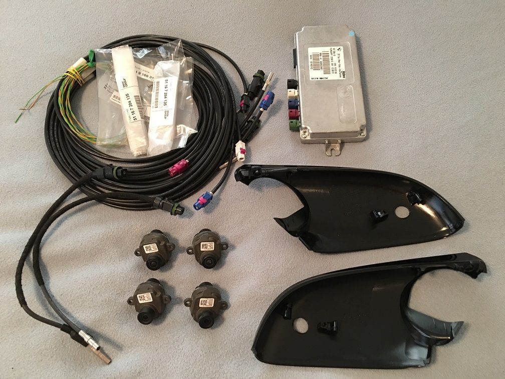 Tools Required: - Dremel - Jack/Jack Stands/Lug Nut Tool (only needed if you feel more comfortable jacking up the vehicle and removing the front wheels to remove the bumper) - Drill with 18mm step/drill bit and 7/32” drill bit - Socket Set with 10mm and 8mm sockets - Hex/T set – This project requires sizes ranging from T-10 to T-35/T-40 - Phillips Head Screwdriver - Flat Screwdriver/Pry tool for removing the plastic expanding rivets - Very Small Flat Screwdriver - Wire Stripper (optional) - Wire connectors/solder depending on your preference (optional) - Standard black electrical tape (optional) - Masking Tape - X-Acto blade/burring tool - Automotive Adhesive Sealant – Clear/Black is fine, your preference. - Rubbing Alcohol/Cleaner Prep Work: - Disconnect Negative Terminal from Battery – Make sure all doors are unlocked, front windows are down, and trunk is open first - Remove the Front Bumper – There are several DIY’s available online about how to do this - Remove Driver and Passenger Side under dash trim panel - Remove the Passenger side trim piece the covers the FEM - Remove the Driver side trim piece in the same location as above. In order to remove this, you will need to use the Phillips Head Screwdriver to remove the handle for the hood release. Make sure the hood is open before doing this step - Remove the 2 covers in the engine bay near the firewall that are covering the DSC/Power Distribution areas Installing the Side View Cameras: Like the Front/Rear PDC or Park Assist retrofit, this step can be slightly nerve-wracking to some people as it does require drilling of the bumper. However, if you go carefully, it should be fine. On the inside of the front bumper, just like the PDC sensors, the bumper should already be marked for where you will drill the openings for the cameras and even has the guides for how the bracket will line up. The Bottom Circle is the location for the Side View Cameras. It is easiest to drill the holes before you attach the brackets. (Note: If you already have the Park Assist system and the brackets are already attached to your car, you will want to follow the below steps for creating the starting hole, however for the 18mm hole, you will want to drill that hole from the outside of the bumper. 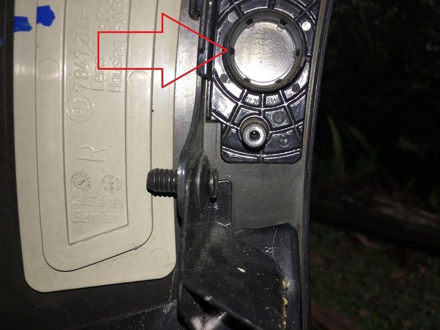 - Place Masking Tape on the outside of the bumper over the area you will be drilling - Using the 7/32” drill bit, start at the dead center of the BOTTOM Circle and create a starter hole - Next, using the 18mm bit, slowly increase the size of the hole, making sure you are still even with the edges of the circle, until you have completely created an 18mm hole - Remove the masking tape from the outside of the bumper, then from the outside, if needed, gently run your X-Acto blade around the edge of the new hole to remove any loose paint “flaps” that are remaining from the drilling process 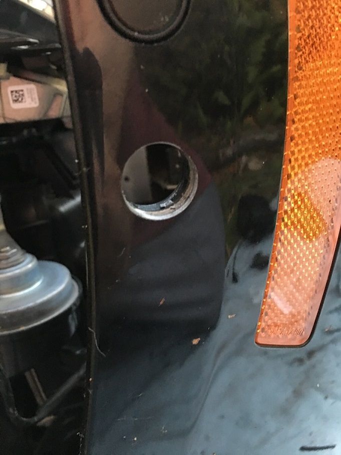 - Once you have completed the drilling, use the rubbing alcohol/cleaner to clean the area around the bracket inside the bumper to ensure proper adhesion - Next, you will want to test-fit a camera to make sure it fits correctly in the new hole. Assuming all fits right, you can remove the covering from the bracket, and carefully place it on the bumper, making sure the hole you drilled lines up with the bottom hole on the bracket, and that the bracket is in line with the markings on the bumper. Once applied and lined up correctly, make sure to press hard for a few seconds to help secure the adhesive to the bumper - After the Bracket is set in place, you can place the camera in the bracket to make sure it is properly aligned, and secure it using 2 screws - Repeat steps for the other side of the bumper 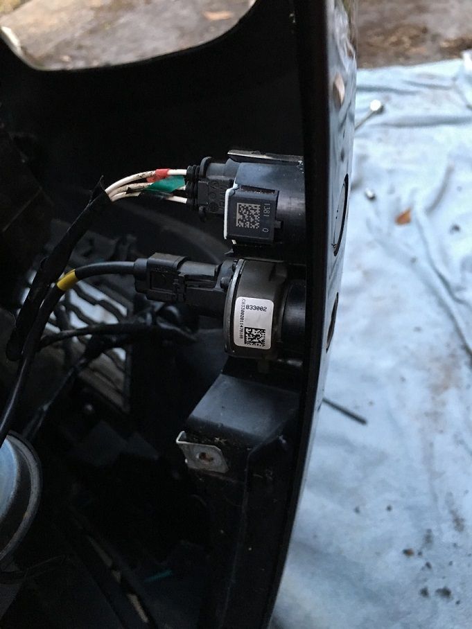 Wiring for the Side View Cameras: This part is relatively easy, since you are simply running the two camera cables from the front to the interior of the car. - Start by removing the connector at the TRSVC end of the cable as shown in the picture below. This makes it easier to run the cable inside the car, and can easily be reconnected once the cable is inside the car. 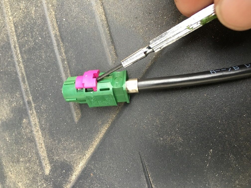 - With the camera cable not connected to the camera, leave about 4 inches of extra slack before you begin running the wiring along the path shown in the pictures below, using either electrical tape or zip ties to secure the cable in place. I found that it is easier to route the cable first, then run it inside the car, as the smaller end is easier to fit through the smaller gaps in the engine bay. Driver’s Side Side View Camera Wiring: 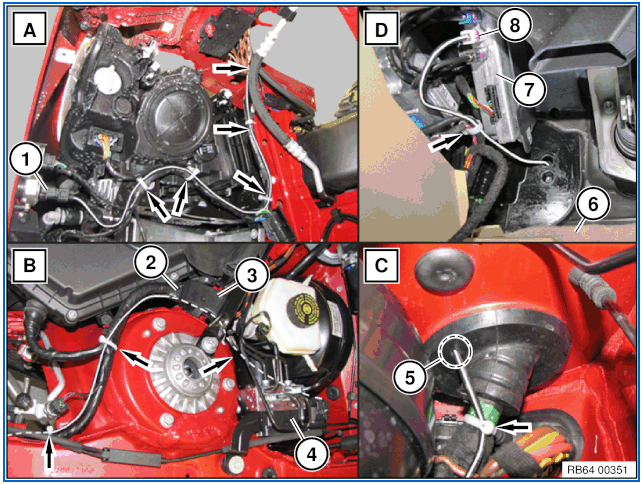 - Once you reach the firewall, you will need to create the hole for the wire to enter the vehicle. Looking under the removed Driver side under dash trim, Rheingold shows two recommended points for running repair wire, as shown below: 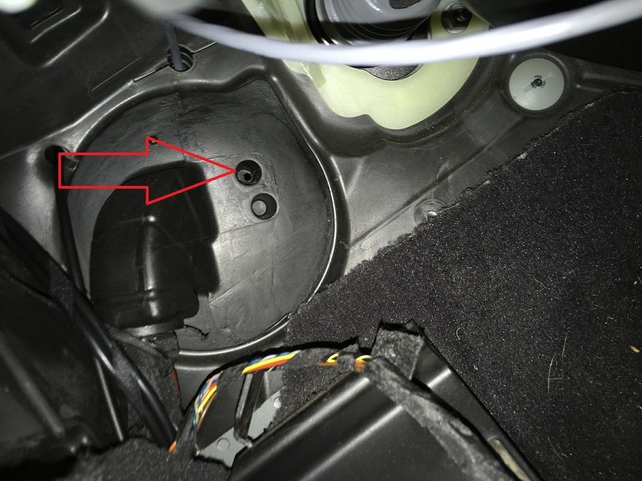 - Using the 7/32” drill bit, use the drill to punch the hole in the wiring grommet from inside the vehicle. - Returning to the engine bay, you should now be able to push the cable through the newly created hole in the grommet. Have patience, as the limited amount of room behind the DSC made this step slightly difficult and full of expletives for me  - After you have pulled all excess wiring through the hole, reattach the connector piece that you removed when you began running the wire. - IMPORTANT: I recommend waiting until you have finished the retrofit and replaced all the vehicle trim to ensure no further movement from the cable, however it is CRITICAL that after you have run the cable, you use the Automotive Adhesive Sealant to seal the opening in the grommet that was created to allow the cable to enter the vehicle. Based on looking at how the F30 windshield drains water, failure to seal this opening may allow water to enter the vehicle. Passenger Side Side View Camera Wiring: 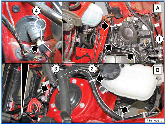 - Once you reach the firewall, you will need to create the hole for the wire to enter the vehicle. Looking under the removed Passenger side under dash trim, Rheingold shows two recommended points for running repair wire, as shown below: 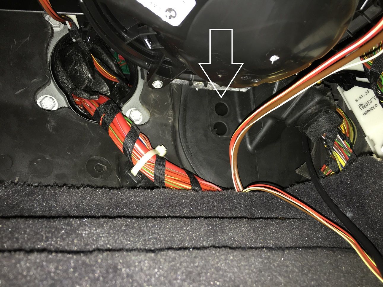 - Using the 7/32” drill bit, use the drill to punch the hole in the wiring grommet from inside the vehicle. - Returning to the engine bay, you should now be able to push the cable through the newly created hole in the grommet. This side is a bit easier, as there is more room to work with on the passenger side of the engine bay. - After you have pulled all excess wiring through the hole, reattach the connector piece that you removed when you began running the wire. - IMPORTANT: I recommend waiting until you have finished the retrofit and replaced all the vehicle trim to ensure no further movement from the cable, however it is CRITICAL that after you have run the cable, you use the Automotive Adhesive Sealant to seal the opening in the grommet that was created to allow the cable to enter the vehicle. Based on looking at how the F30 windshield drains water, failure to seal this opening may allow water to enter the vehicle. Top View Camera Installation: I started with the passenger side first, and found it easiest to start with installing the mirror wiring and camera, then working through the door, then inside the car to the TRSVC. - To get started, you will need to remove the door panel on the vehicle. This is a relatively simple process, with tutorials available on the internet. Simply pry off the trim piece on the door(the CF-wrapped piece shown here), then remove the two Hex screws inside the handle. Once those are removed, start at one end and begin prying the door panel loose. Once the panel is loose, you can lower it down, you do not need to remove/disconnect any cables/connectors. Next, loosen the trim piece that houses the tweeter by pulling it towards you, this will expose the mirror connector and 3 Hex Bolts that secure the mirror to the door. Don’t remove these yet! Installing the mirror cable/camera: I found it easiest to complete the initial installation with the mirror still attached to the car, as it holds it in place while you are working. - To start, use a small pry tool to gently pop the mirror glass out of place. Depending on which options you have, if the mirror glass is connected with a couple wires, it will rest in place on the door without needing to be removed completely, as shown in the pictures below - Next, gently pull the painted mirror cap cover off to expose the exterior inside of the mirror where the camera/cable will be installed - You will now need to remove 3 T-10 hex screws to loosen the bottom mirror shroud to install the camera. The screws are circled in the below pictures 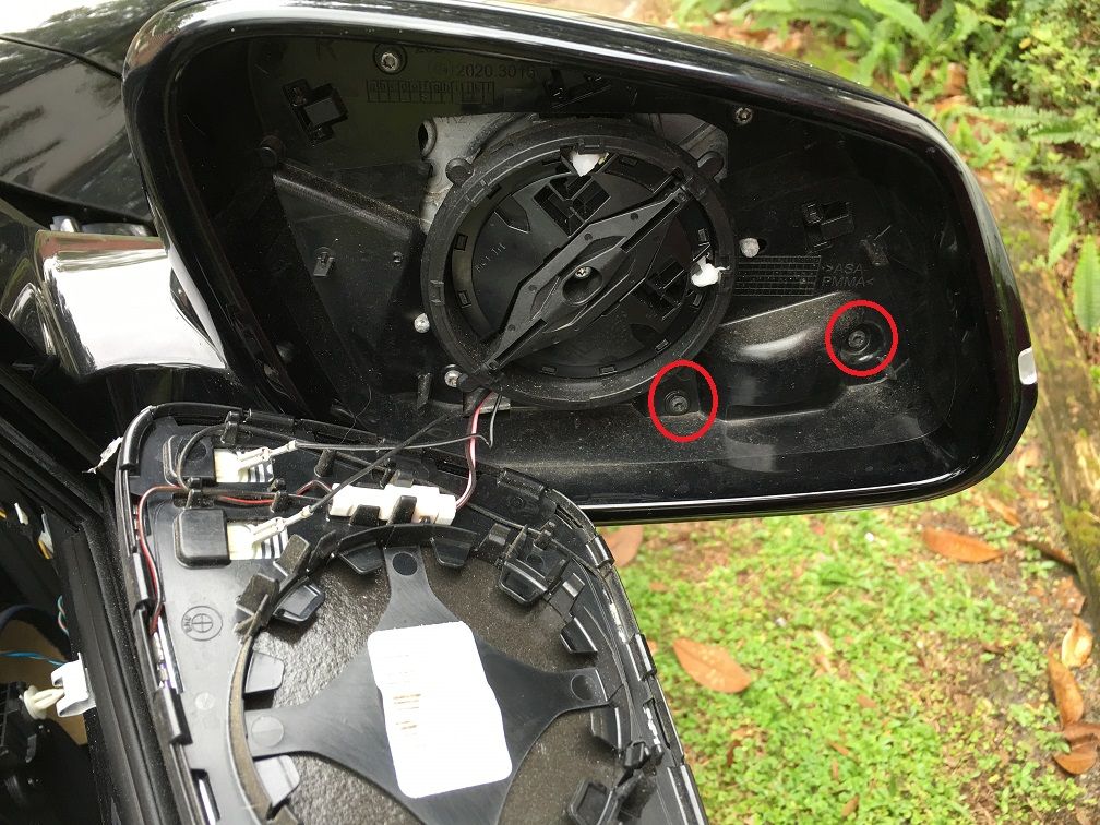 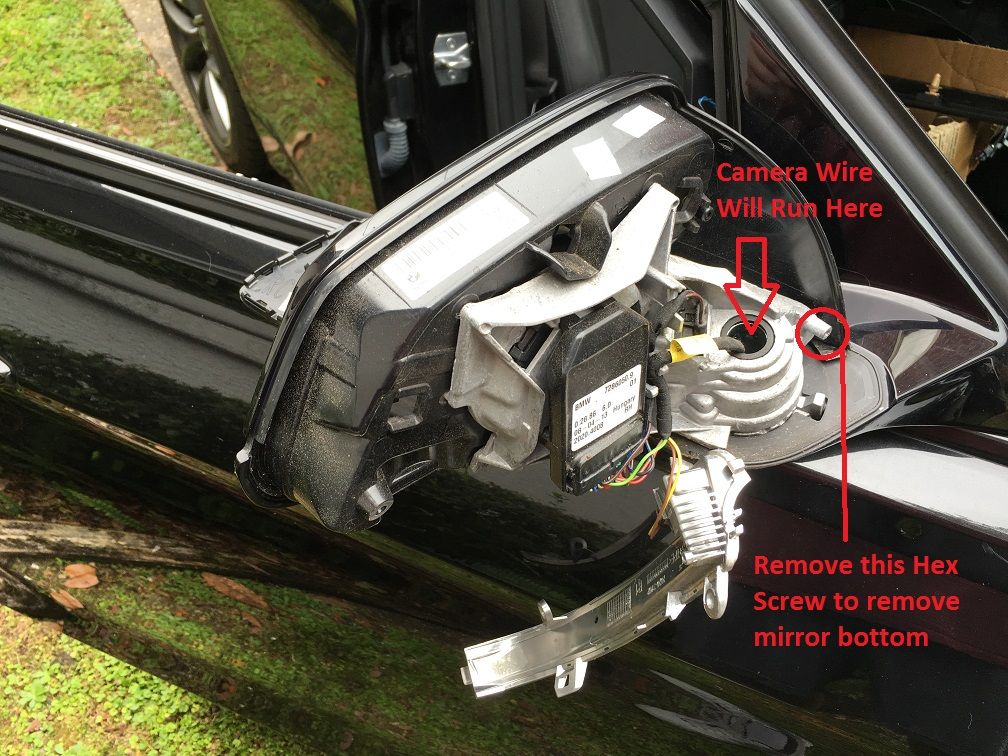 - Once you have removed the hex screws, at the outer edge of the mirror, push down on the bottom of the mirror shroud to pop it loose. Then, pull it away from the vehicle, and it will slide out towards you. The LED Turn Indicator will also easily slide out of the mirror bottom - On your new mirror bottom, using two of the small dark screws included in the mirror screw set, secure the camera to the bottom shroud as shown below 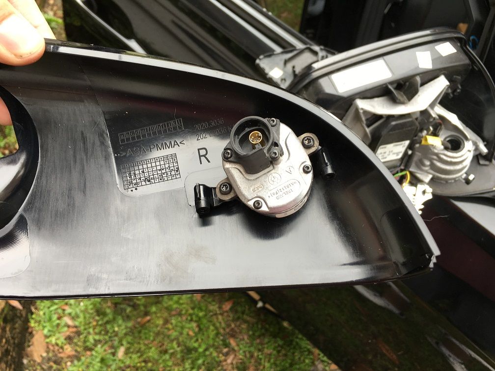 - Reattach the LED Turn Indicator to the bottom of the mirror by sliding it into place - You can now slide the new mirror bottom shroud back under the mirror, and gently push up until you hear it click into place - Replace the 3 hex screws to secure the mirror bottom into place - You can now pop the mirror glass back into place by aligning it to the mirror and pressing gently until you hear it click back into place. Do not reattach the painted mirror cap cover yet!! - Now you will detach the mirror from the car. Disconnect the wiring connector from the door, then remove the 3 large hex bolts that hold the mirror in place. Make sure you have one hand under the mirror as you remove the last screw to prevent your mirror from falling to the ground! - Once you have removed the mirror, you will need to gain access to the wiring path. On the bottom of the mirror, you will notice a small round cap with three tiny holes as shown below. I’m sure there is a special tool used to remove this, but it isn’t needed. Using your T-10 bit, insert it into one of the smaller holes circled in the picture. Using a small amount of downward pressure, push the cover counter-clockwise. This will turn the cover loose, giving you access to the bottom of the mirror. 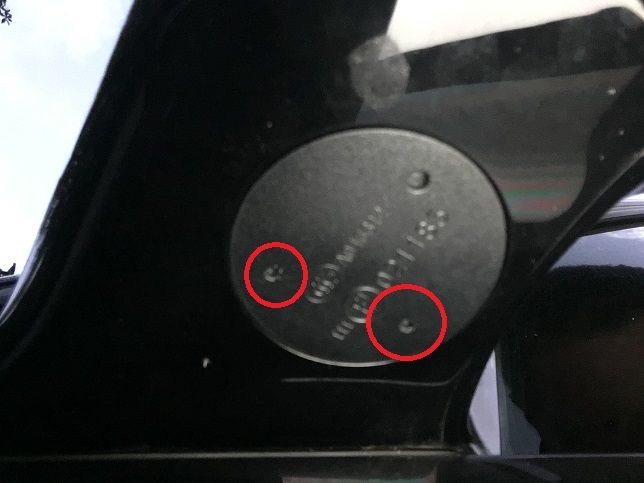 - Next, you will need to loosen the connector on the mirror that runs to the inside of the car. Using a very small flat head screwdriver, you can loosen the two tabs holding it in place as shown below. 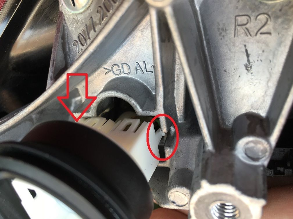 - Once the connector is loose, you will need to drill out the opening for the HSD wire to be able to fit into the connector. Using the 7/32” drill bit, drill through the large circular hole to the left of the existing pin connectors. You will need to make sure that you have drilled it out enough that you can hear the cable click into place and be secure once you insert it into the connector. - Now you can feed the small end of the mirror HSD cable into the hole shown several pictures above. Route the cable to the connector and insert it into place, with the tab on the HSD wire connector facing up. If you have drilled the hole successfully, you will feel the connector click into place and it will be secured into place if you try to pull it back out without depressing the tab. - Once you have inserted the HSD cable into the connector, replace the connector back into its spot in the mirror. Finish routing the HSD wire to the camera in the mirror, and connect it - Reattach the painted mirror cap cover onto the mirror - Reattach the mirror to the door and replace the 3 large hex bolts to secure it into place Installing the door wiring: - This part is one of the easiest steps in the process. Start by disconnecting the door wiring harness from the body of the car by pulling up on the tab below. Once you have pulled it up enough, it will come loose and slide out. 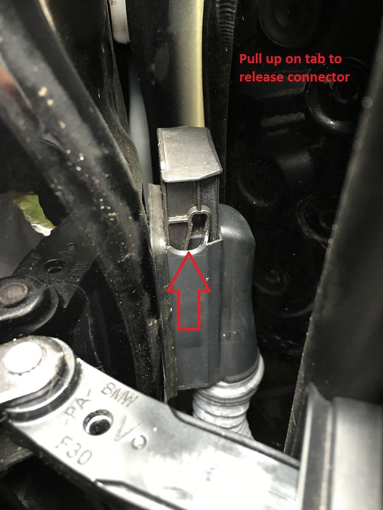 - Take the custom HSD Wire you ordered and remove the connector cap from both ends of the cable as you did for the Side View cameras, except you can discard these as you will not need them. You will need to use a flat head screwdriver to pry the cap off of the right angle connector. - Going slowly to avoid tearing the material, gently pull back the foam-like material from the door on the end closed to the car. Try to keep as much of the adhesive in place as possible so that it will resecure properly once you are finished. - Now you will need to pull the wiring harness loose from the door to help with running the wiring through to the connector, as shown below 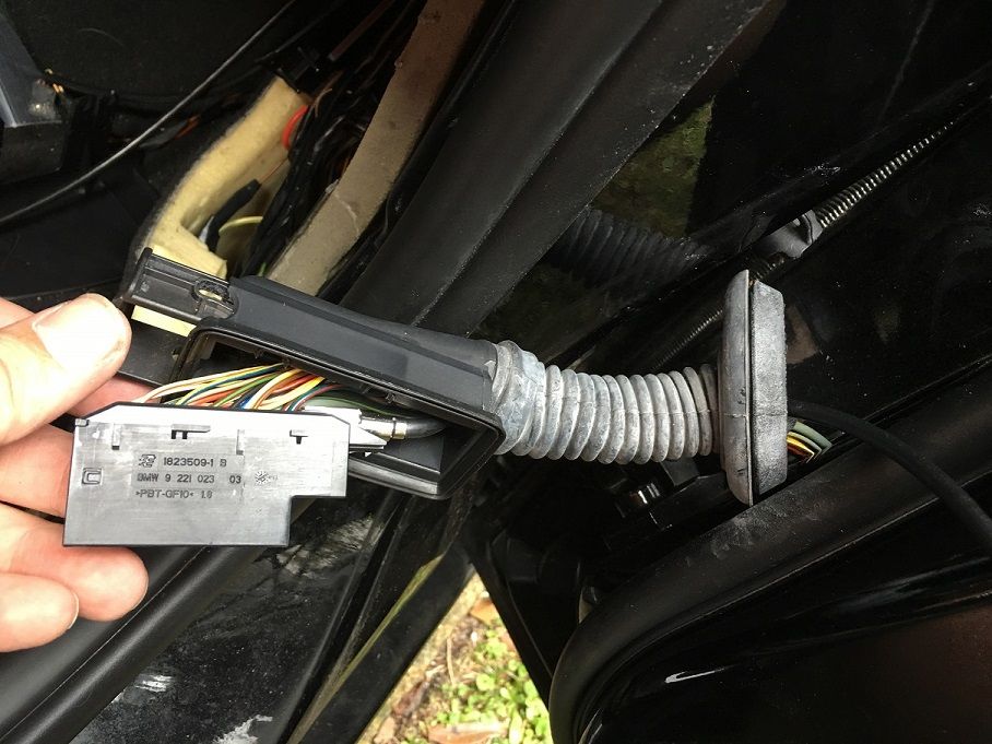 - Insert the right angle end of the cable into the connector as shown above, and then run the cable through the rubber tubing - Route the cable through the opening to the top left of the door - Insert the straight end of the cable into the connector that will connect to the mirror - After you have connected both ends of the cable, you will need to zip-tie any excess cable and tuck it away inside the door - Replace the grommet from the wiring tubing to the door, but do not yet reattach the connector to the body of the car - You can now replace the tweeter trim on the door, then replace the door panel, making sure to push all plastic rivets back into place and replace the two hex screws in the door panel to secure it in place. Installing the interior Side View Camera cabling: The process will be the same for both sides of the vehicle, however on the Passenger side you will need to slightly move the FEM out to gain access to the connector. This is relatively easy and does not require you to disconnect anything from the FEM: - Remove the screw holding the dark gray/black cover in place over the FEM, then remove the silver screw shown below which holds the FEM in place: 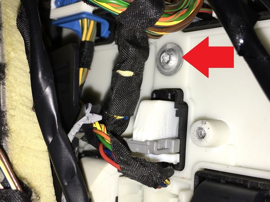 - Once the screw is removed, you can gently pull the FEM forward to gain access to the door connector, shown here: 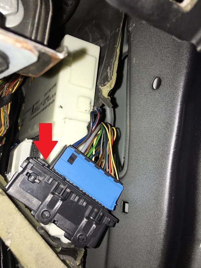 - Once you have access to the connector, the square block indicated by the arrow is where you will insert the HSD wire. Here is where it got a little tricky for me. Despite ordering the Custom HSD wire following the 1-4. 2-3. 3-2. 4-1 pin connections as per BMW standards, the cables did not initially connect properly until I rotated the interior cable by 90 degrees. So here is what I did: 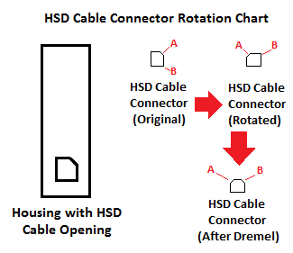 - The initial corner with the angle by default faces top right, and is marked in the picture as Corner A. Rotate the cable connector 90 degrees counter clockwise so that Corner A faces top left. Using the Dremel, wear down the edge of Corner B. Once you have sanded the edge down, Corner B should be the edge that matches up with the angled slot in the housing in order to get the proper connection - Additionally, the right angle end piece that came on the Custom HSD wire was not long enough to complete the connection when both cables are inserted into their connectors. In order to ensure proper connection, use the 7/32” drill bit to drill into the connector housing slot so that the HSD wire can connect to the HSD wire from the door - Once the connection has been made, you can re-attach the Door Wiring Harness and press down on the tab to secure it in place - Move the FEM back into place, and replace the 2 hex screws - Repeat for the Driver’s Side of the vehicle, minus the steps involving the FEM Wrapping up physical installation: You should now have all 4 new camera cable wires ready to connect to the TRSVC. If you didn’t already, run the Passenger side cables to the Driver’s Side as shown in the original post. Remove the original Rear View Only TRSVC, and connect the harness and all 5 camera cables to the new Surround View TRSVC. Also, go ahead and replace the Center Console Switch with the new switch. I recommend performing the coding and testing to make sure everything works before you replace all vehicle trim in case you have to go back and redo something. At this point, all connections are completed and everything physically should be in place, now on to the coding! Vehicle Coding: - Reconnect the Negative Battery Terminal to restore power to the car - Connect to the car via E-Sys. After connecting, the first step will be to add Option 5DL to your FA. Follow the steps in the E-Sys learning guides if you are unfamiliar with how to complete this step - Once you have updated your FA with the new option code, you will need to create a Cafd file for your new TRSVC Module. However, you will need to know your car’s current I-Step Level first - To find this, go to the Expert Mode-VCM Screen. Under I-Steps, click Read. Your current I-Step level will then be displayed, as shown below. Take down this information, and save for future reference if needed. SHOWN FOR ILLUSTRATIVE PURPOSES ONLY: - Now, you can create the Cafd file. On the Expert Mode-Coding screen, if you click Read (ECU), you should now see the new TRSVC listed as one of the modules on your car. However, if it was bought brand new, it will most likely be missing the Cafd file. Highlight the TRSVC, then click Detect CAF for SWE. When the window shown below comes up, you may have several options available: SHOWN FOR ILLUSTRATIVE PURPOSES ONLY - NOT ACTUAL TRSVC MODULE CODING: - You will need to select the option that matches your car’s current I-Step Level. Select the correct option and hit Ok. This should create the Cafd file for the TRSVC. - Now all that is left is to VO Code the updated FA to the car. Activate the FA. At this point, you will need to code the FEM, REM, HU_CIC/NBT, TRSVC, ICM, and PMA(if equipped) modules. Personally, whenever I complete a retrofit, I recode all modules in the car in the event that there is something related to the new retrofit in that module that may have been missed. How you code is up to you, but by coding them all, it avoids the risk of missing something. Reassembly of the car: Once you have completed all coding, turn the car off, then back on. You should now see the Side View Cameras come on when you press the Camera button on the center console. If you put the vehicle in reverse or press the Parking Aid button, you will see the Top View Camera come on. Assuming all checks out with no errors, you can re-assemble all of the trim panels and reattach the front bumper to the car. DON’T FORGET to apply sealant to the wiring access point in the firewall!!! Notes/Observations from use: Surprisingly, I have found myself using the Side View cameras more than I thought I would, especially in areas where my view of oncoming traffic is blocked by parked cars. As for Top View, let's just say I have a new hobby of trying to be perfectly aligned in the parking spot all the time  Last edited by roxxor; 02-25-2016 at 02:17 PM.. |
| 06-12-2016, 01:52 AM | #41 |
|
Coding ECU's remotely
448
Rep 1,179
Posts |
Awesome write up! Finding an F31 with the cameras is nearly impossible, so this will be first on my retrofit list.
__________________
Author of Car Connector - remote ICOM & ENET tool - Built in VPN for easy coding and remote diagnostics
Car Connector on YouTube |
|
Appreciate
0
|
| 06-19-2016, 07:02 PM | #42 |
|
Private First Class

44
Rep 118
Posts |
Excellent job Roxxor and Hrv - congrats
It really pushes me to take action, but I'm little afraid by the quantity of job hours.. About parts, I only have Rear PDC currently on my F30, it will be the same list as yours Roxxor ? |
|
Appreciate
0
|
| 06-19-2016, 10:20 PM | #43 | |
|
Major
1151
Rep 1,148
Posts |
Quote:
|
|
|
Appreciate
0
|
| 06-20-2016, 03:16 AM | #44 |
|
Private First Class
44
Rep 118
Posts |
Yes- I see.
About front PDC, is there a relationship if I decide to do both retrofits in same time ? My question is specially about wiring and control unit |
|
Appreciate
0
|
Post Reply |
| Bookmarks |
|
|


.jpg)


