Hello all! Just wrapped up my retrofit of the Parking Assist on my 2013 F30 sedan a couple weeks ago, and figured I would post the write-up so others can do the same! Total cost for this ended up being around the same as if it had been ordered from factory, roughly $500-$550, if you can find good deals on the auction sites on the parts then it makes it relatively reasonable.
DISCLAIMER:
As with all DIY projects, undertake this at your own risk. I am not responsible for anything that happens to you or your car! Given that this particular system does automate the steering of the vehicle while parallel parking, as BMW reiterates in the on-screen Owner’s Manual, you are still responsible for braking, acceleration, and maintaining an awareness of the proximity of your car to other objects, including other vehicles, curbs, etc. With that said, on to the write-up!
Pre-Requisites:
In order to successfully add this to your vehicle, you will, at a minimum, need to have Front and Rear Park Distance Control (Option 508) and Rear View Camera (Option 3AG). Factory or retrofitted does not matter. Also, this retrofit does require VO coding, so you will need a computer with an ENET cable and should be familiar with E-Sys coding and preferably Rheingold as well.
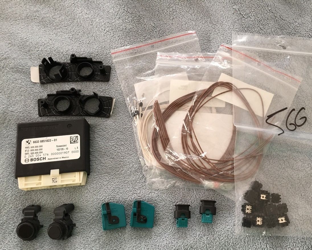
Parts List: (Part #’s may vary per vehicle. Parts listed are for a US F30 sedan. Check RealOEM or ETK to confirm correct Part #’s for your vehicle. Also, some wiring will vary in color due to the incorrect parts being shown in the picture below)
Main Parts:
- DSC Pulse Generator, front – Qty. 2 – 34526791224 (If your vehicle already has ACC with Stop and Go (Option 5DF), or you have an M3, then you will not need to replace these)
- PMA Park Assist Control Unit – 66336851822 / 66336857208 / 66336860827 / 66336864898 (multiple part #’s available for this, but all are interchangeable)
- Ultrasonic Park Assist Sensor - Qty. 2 – These sensors are different from the ones used for the Front/Rear PDC. This part number will vary based on your car’s color. You can find the correct part # for your paint code here
http://www.realoem.com/bmw/enUS/show...diagId=66_0287
- Decoupling Ring - Qty. 2 – 66206923000
- Brackets for Park Assist Sensors – Included in 51117324343 (If you retrofitted the Front PDC system, or if you have Surround View (Option 5DL), you should already have the brackets and will not need to order this)
Sensor Wiring:
- Connector, 3 POL. – Qty. 2 – 61136925599
- Socket Contact w/ Grommet – Qty. 6 – 61130005199
- BMW OEM Quick Connects – Qty. 6 – 61138364566
PMA Wiring:
- Socket Contact – Qty. 20 – 61130005197 (At a bare minimum, you will need 8. However, If you have to extend the wiring from your factory PDC wires, you will need 20)
- Socket Housing, 18 Pin – Qty. 2 – 61138364666
- Covering Cap – Qty. 2 – 61138364662
 Tools Required:
- Dremel
- Jack/Jack Stands/Lug Nut Tool
- Drill with 18mm step/drill bit and 7/32” drill bit
- Socket Set with 10mm and 8mm sockets
- Hex/T set – This project requires sizes ranging from T-20 to T-35/T-40
- Flat Screwdriver/Pry tool for removing the plastic expanding rivets
- Very Small Flat Screwdriver
- Wire Stripper
- Wire connectors/solder depending on your preference
- At least 2 different colors of 18 gauge wire (you can use up to 4 colors, or use different color electrical tape/labels to identify wires)
- Standard black electrical tape
- 4 different colors of electrical tape (I used 6 (including black) during this retrofit)
- Masking Tape
- X-Acto blade/burring tool
- Automotive Adhesive Sealant – Clear/Black is fine, your preference.
- Rubbing Alcohol/Cleaner
Prep Work:
- Disconnect Negative Terminal from Battery – Make sure all doors are unlocked and trunk is open first
- Remove the Front Bumper – There are several DIY’s available online about how to do this
- Remove Passenger Side under dash trim panel
- Remove all floor trim pieces along the Passenger side of the vehicle
- Remove Passenger Side Rear Seat Bolster – Just pull it towards you, then slide up to remove
- Remove Passenger Side Trunk Lining – This requires removing 3 plastic rivets and removing the Tie Down Ring using a Hex bit. The lining will then slide out at an angle.
- Create a PMA Sensor wire set using two 18 gauge wires for the two Signal wires for the Parking Assist Sensors. This will need to be around 25-30 feet to run from the Front Bumper to the rear of the car, and the wires will need to be different colors to help with identification. For the ease of this write-up, I will refer to the wire colors I used, which were Blue and Green. The Blue wire, which runs to the Driver’s Side Sensor, will need to be around 5-6 feet longer than the Green wire. I placed the two wires together and wrapped the entire length with electrical tape, however you can go about this step however you see fit.
- Create a K-Can wire set using 4 of the socket contacts (61130005197). I did not get a picture of this, but it is very simple. Take 2 of the contacts, and using a wire connector/solder, connect them together. Repeat. The end result is that you should have two wires with a connector at each end that are about 1.5-2 feet long. Once you have the two wires, use a piece of colored electrical tape(I used Yellow and White) to mark the wires at each end. Then, I wrapped the length in electrical tape so that there weren’t two loose wires.
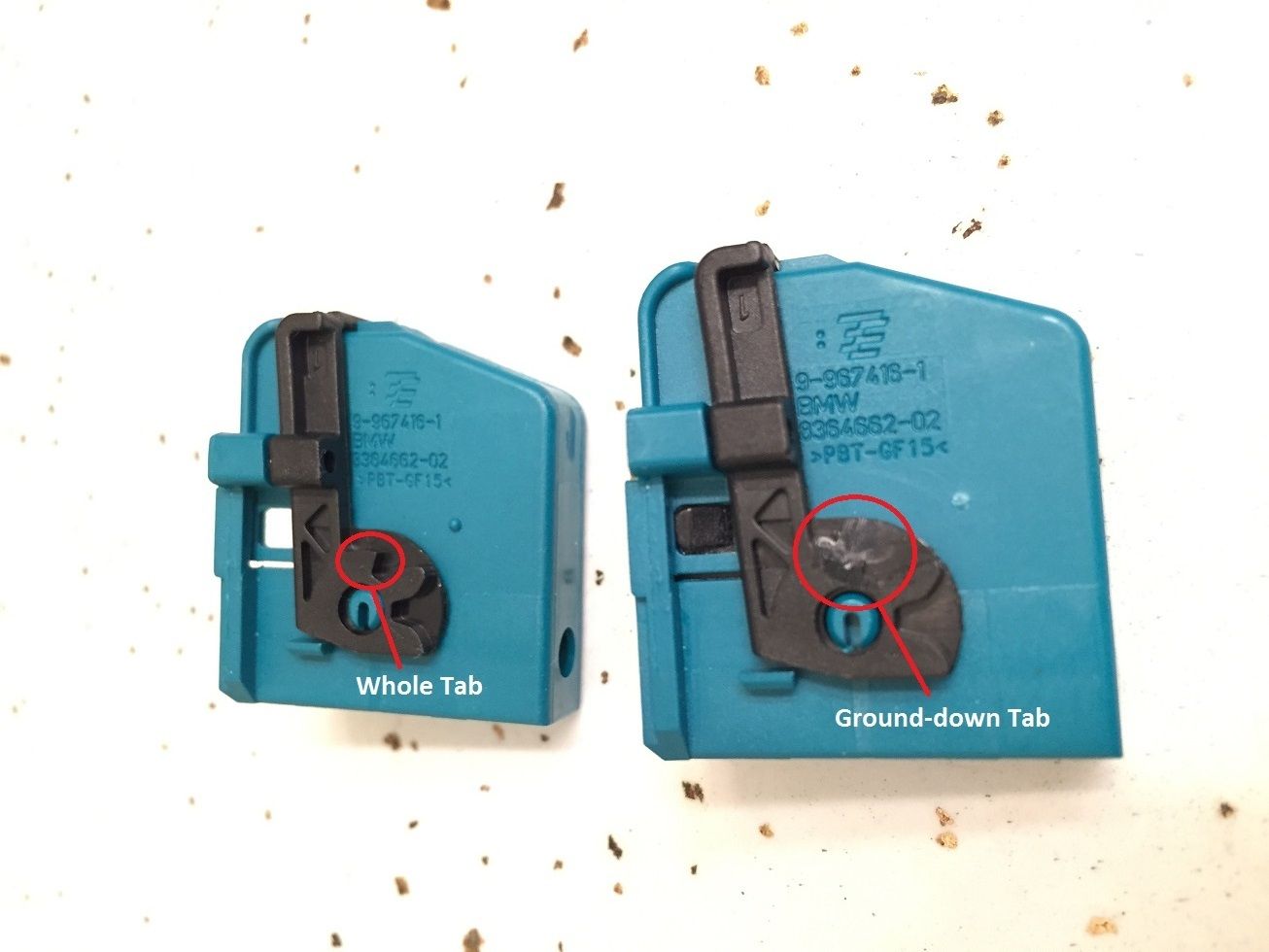
- On the Covering Caps for the PMA Module wiring, the black bar-like piece that holds the connectors in place has an extra tab that will need to be removed in order to allow the connector to properly seat inside the PMA module. Using the Dremel, you will need to remove the innermost tab on the black piece as shown below. Repeat for the other side of the connector, then repeat for the second connector. You can test fitment of the connector before you move on to ensure you have removed enough of the tab.
 Install the PMA Control Module:
Easiest step in the process, and will give you an idea of where you will need to run your wires to later on. Place the module in the bracket(just slides in) as shown below
Swapping the DSC Pulse Generators:
This is required for vehicles which do not already have the Active Cruise Control with Stop & Go installed. Relatively easy swap, doesn’t matter what stage this is done at as long as you do it while the battery is disconnected.
- Jack the front end of the car up and remove the front two wheels (This could possibly be completed without removing the wheels, but you would have a very limited amount of room to work in.
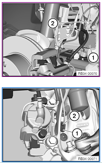
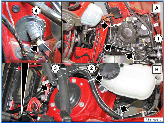
- Behind the hub, you will find the DSC Generator attached to the backside of the hub with a Hex bolt (#1 in the bottom picture below). Remove the bolt, and pull the old generator (#2 in the bottom picture) out.
- Insert the new generator, and re-attach the Hex bolt.
- Taking the new generator cable, use it to follow along the route of the old cable (shown in the top picture as #2), attaching where the old cable attaches.
- Open the plastic box that houses the connector. Remove the old connector by pulling up, and then connect the new connector and close the plastic box.
- Repeat for other side, then replace the wheels and lower the car, remembering to tighten the wheels.
 Installing the Front Sensors:
This can be the most intimidating part for some as like the Front/Rear PDC retrofit, it does require drilling of the bumper. However, if you go carefully, it should be fine. On the inside of the front bumper, just like the PDC sensors, the bumper should already be marked for where you will drill the openings for the sensors and even has the guides for how the bracket will line up. The Top Circle is the location for the PMA Sensor. It is easiest to drill the holes before you attach the brackets. (Note: If you already have the Surround View system and the brackets are already attached to your car, you will want to follow the below steps for creating the starting hole, however for the 18mm hole, you will want to drill that hole from the outside of the bumper.
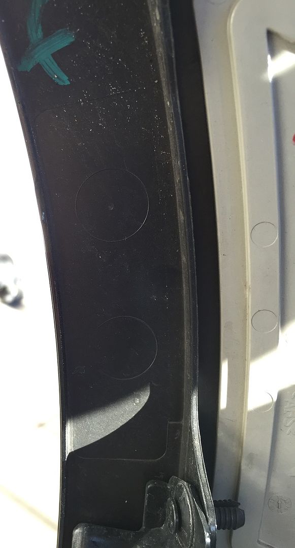
- Place Masking Tape on the outside of the bumper over the area you will be drilling
- Using the 7/32” drill bit, start at the dead center of the TOP Circle and create a starter hole
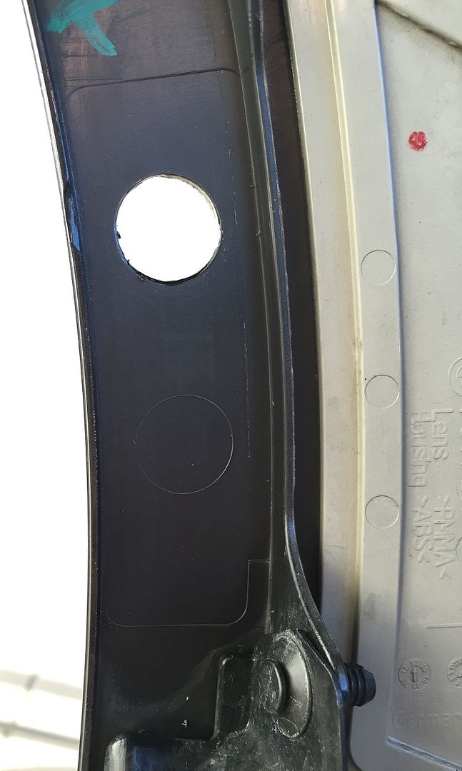
- Next, using the 18mm bit, slowly increase the size of the hole, making sure you are still even with the edges of the circle, until you have completely created an 18mm hole
- Remove the masking tape from the outside of the bumper, then from the outside, if needed, gently run your X-Acto blade around the edge of the new hole to remove any loose paint “flaps” that are remaining from the drilling process
- Once you have completed the drilling, use the rubbing alcohol/cleaner to clean the area around the bracket inside the bumper to ensure proper adhesion
- Next, you will want to test-fit a sensor(with the decoupling ring in place) to make sure it fits correctly in the new hole. Assuming all fits right, you can remove the covering from the bracket, and carefully place it on the bumper, making sure the hole you drilled lines up with the top hole on the bracket, and that the bracket is in line with the markings on the bumper. Once applied and lined up correctly, make sure to press hard for a few seconds to help secure the adhesive to the bumper
- After the Bracket is set in place, you can place the sensor in the bracket to make sure it is properly aligned
- Repeat steps for the other side of the bumper
Wiring for the Front Sensors:
This part is relatively easy, since most of the wiring connections take place on the Front PDC wiring harness. You will only be running 2 wires to the back of the vehicle to the PMA module.
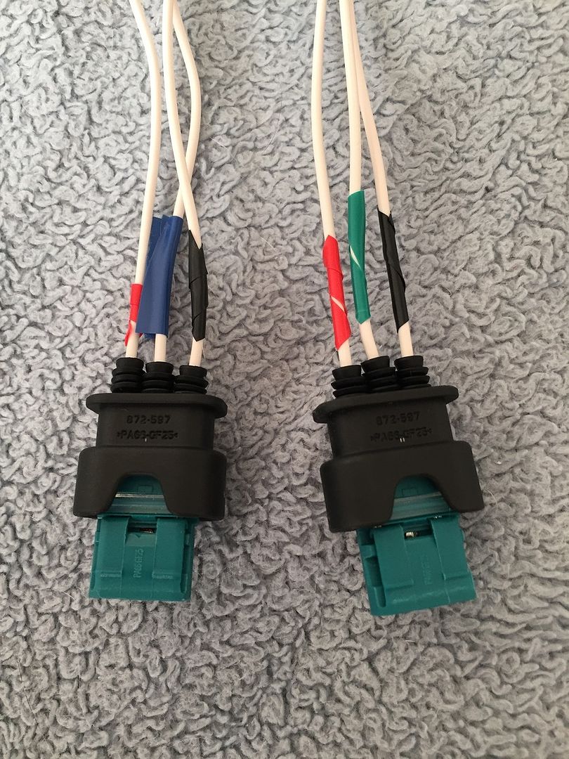
- Place the Socket Contact w/ Grommets into the 3-Pin Connector. Note that the grommets should be pushed all the way in, however I ordered the wrong part initially so they were too big to fit all the way inside the housing. The part # listed in the parts is the correct one. Using Electrical tape, with the socket facing you, mark the three wires as shown below, with the left wire(Power) in Red, center wire(Signal) in Blue(left connector)/Green(right connector), and the right wire(Ground) in Black. The two Center Wires will need to be marked with different colors so that you can identify which wire is for which side when you run the wires to the rear of the car
- Once you have your marked wiring on the connectors, you will need to peel back the tape on the PDC wiring harness near the Driver Outer Sensor (far left) and the Passenger Outer Sensor (far right) so that you can make the power/ground connections. Using the wire stripper and the OEM Quick Connects, connect the following for both the Driver and Passenger side connectors:
- PMA Power Wire (wire you marked with Red) to PDC Power Wire (Green/White)
- PMA Ground Wire (wire you marked with Black) to PDC Ground Wire (Brown/White)
- Secure/wrap the quick connectors with electrical tape
- Using a wiring connector/solder, connect the Left(Driver) PMA Signal Wire (wire you marked in Blue) to the Blue wire from the wire set you created during the Prep Work. Secure the length of the Blue Wire to the PDC Wiring Harness until you reach the Passenger side connections.
- Using a wiring connector/solder, connect the Right(Passenger) PMA Signal Wire (wire you marked in Green) to the Green wire from the wire set you created during the Prep Work. Secure the rest of the length of the wire set to the PDC harness.
Result should look similar to this:

- Run the wiring for the harness along the path shown in the below pic from Rheingold, making sure to zip tie/wrap with electrical tape every so often to secure the wire as you move towards the firewall.
- Once you reach the firewall, you will need to create the hole for the wire to enter the vehicle. Looking under the removed Passenger side under dash trim, Rheingold shows two recommended points for running repair wire, as shown below:
- Using the 7/32” drill bit, use the drill to punch the hole in the wiring grommet from inside the vehicle.
- Returning to the engine bay, you should now be able to push the wire set through the newly created hole in the grommet.
- After you have pulled all excess wiring through the hole, run the wiring along the passenger side floor, following the factory wiring until you reach near the REM module in the Trunk.
- IMPORTANT: I recommend waiting until you have finished the retrofit and replaced the passenger side trim to ensure no further movement from the wire, however it is CRITICAL that after you have run the wire, you use the Automotive Adhesive Sealant to seal the opening in the grommet that was created to allow the wires to enter the vehicle. Based on looking at how the F30 windshield drains water, failure to seal this opening may allow water to enter the vehicle.
Preparing the PMA Module Trunk Area Wiring:
This part is fairly straightforward as long as you remember to label/identify your wires correctly. You will be connecting a power and ground wire, and adding connector ends to the two PMA signal wires you ran from the front of the car.
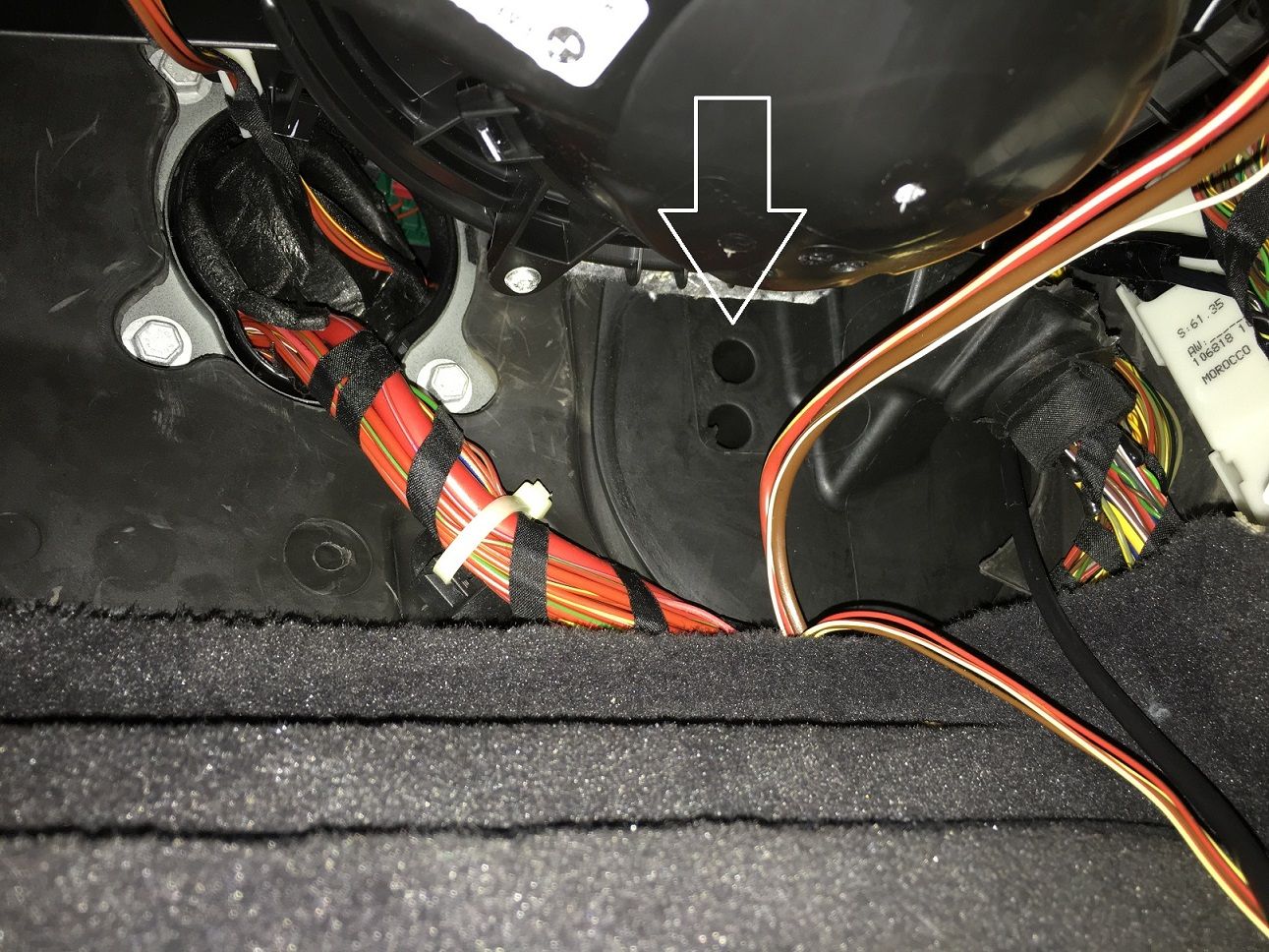
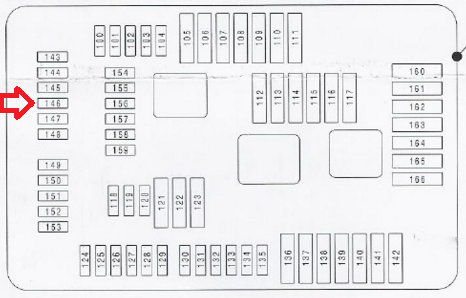
- Remove the 10mm socket nut that is holding the rear fuse block in place. On the underside, look for the wire coming from Fuse #F146. Using an OEM Quick Connect, connect a piece of 18 gauge wire (preferably red) and run it to near the PMA Module. Using a wire connector/solder, connect one of the Socket Contacts (61130005197) to the red wire and mark it at the end near the connector with red electrical tape to help with identifying it as the power wire.
- Next, locate the large grounding point above and to the left of the PMA Module location. Using the last remaining OEM Quick Connector, connect a piece of 18 gauge wire (preferably black) to any of the grounding wires coming from the ground point. Extend this wire to the PMA Module area, then using a wire connector/solder, connect one of the Socket Contacts (61130005197) to the black wire and make sure you are able to identify it as the ground wire for later reference.
- Take the end of the 2-wire set that you ran from the front of the car(Blue and Green wires). Using a wire connector/solder, connect one of the Socket Contacts (61130005197) to each wire, and then mark the socket contact near the connector using Blue and Green electrical tape so that you can identify these wires as the PMA sensor signal wires.
Connecting the PMA Module wiring:
In this step, you will be placing the wiring socket contacts into their appropriate spot in the 18-pin Socket Housing connectors, including relocating the PDC wires from the REM to the PMA. The color coding information in these steps is largely dependent on following the colors I referenced above. If you have used different colors, make sure you notate these changes as you complete the process to ensure correct wiring. Additionally, depending on your car’s wiring, there may not be enough slack on the factory wires to reach from their original location to the PMA module location. If needed, use the remaining Socket Contacts (61130005197) to extend the wires, making sure to document which wire is which for connecting to the PMA, or extending them one at a time and connecting them to the PMA connectors as you go.
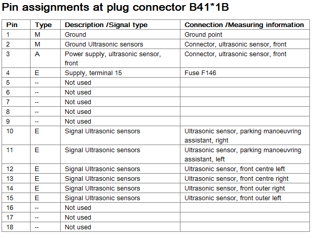
Connector #1 – B41*1B: (Wiring chart below)
- Pin 1 – Ground – Connect the wire that you ran from the grounding point to this slot
- Pin 2 – Front PDC Ground Wire – Move the Brown/White wire from REM Pin 36 to this slot
- Pin 3 – Front PDC Power Wire – Move the Green/White wire from REM Pin 48 to this slot
- Pin 4 – Power – Connect the wire that you ran from the Rear Fuse Block to this slot
- Pin 10 – PMA Sensor Signal, Right – Connect the GREEN wire that you ran from the front of the car to this slot
- Pin 11 – PMA Sensor Signal, Left – Connect the BLUE wire that you ran from the front of the car to this slot
- Pin 12 – PDC Sensor Signal, Front Center Left – Move the Blue/Green wire from REM Pin 52 to this slot
- Pin 13 – PDC Sensor Signal, Front Center Right – Move the Blue/Black wire from REM Pin 40 to this slot
- Pin 14 – PDC Sensor Signal, Front Outer Right – Move the Blue/Brown wire from REM Pin 41 to this slot
- Pin 15 – PDC Sensor Signal, Front Outer Left – Move the Blue/Purple wire from REM Pin 53 to this slot
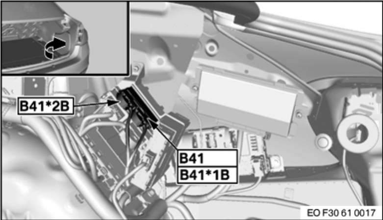
- Once you have completed all connections, slide the Covering Cap over the Socket Housing (will only fit on one way). Then, place in the B41*1B socket as shown in the PMA Module Location Picture above. Wiring should be coming out of the connector in the direction of the rear of the vehicle.
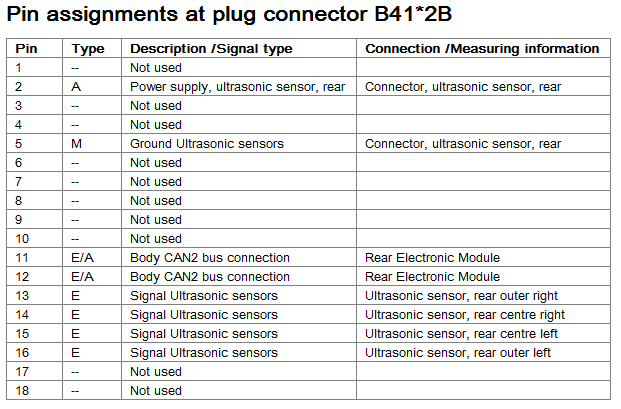
 Connector #2 – B41*2B: (Wiring chart below)
- Pin 2 – Rear PDC Power Wire – Move the Green/Black wire from REM Pin 49 to this slot
- Pin 5 – Rear PDC Ground Wire – Move the Brown/Black wire from REM Pin 37 to this slot
- Pin 11 – PMA K-Can Signal Wire – Using the K-Can wire set created during the Prep Work, connect one end of the wire marked with WHITE to this slot. Then, connect the other end to REM Pin Slot 29
- Pin 12 – PMA K-Can Signal Wire - Using the K-Can wire set created during the Prep Work, connect one end of the wire marked with YELLOW to this slot. Then, connect the other end to REM Pin Slot 44
- Pin 13 – PDC Sensor Signal, Rear Outer Right – Move the Yellow/Brown wire from REM Pin 39 to this slot
- Pin 14 – PDC Sensor Signal, Rear Center Right – Move the Yellow/Black wire from REM Pin 38 to this slot
- Pin 15 – PDC Sensor Signal, Rear Center Left – Move the Yellow/Green wire from REM Pin 51 to this slot
- Pin 16 – PDC Sensor Signal, Rear Outer Left – Move the Yellow/Purple wire from REM Pin 50 to this slot
- Once you have completed all connections, slide the Covering Cap over the Socket Housing (will only fit on one way). Then, place in the B41*2B socket as shown in the PMA Module Location Picture above. Wiring should be coming out of the connector in the direction of the rear of the vehicle.
At this point, all connections are completed and everything physically should be in place, now on to the coding!
Vehicle Coding:
- Reconnect the Negative Battery Terminal to restore power to the car
- Connect to the car via E-Sys. After connecting, the first step will be to add Option 5DP to your FA. Follow the steps in the E-Sys learning guides if you are unfamiliar with how to complete this step
- Once you have updated your FA with the new option code, you will need to create a Cafd file for your new PMA Module. However, you will need to know your car’s current I-Step Level first
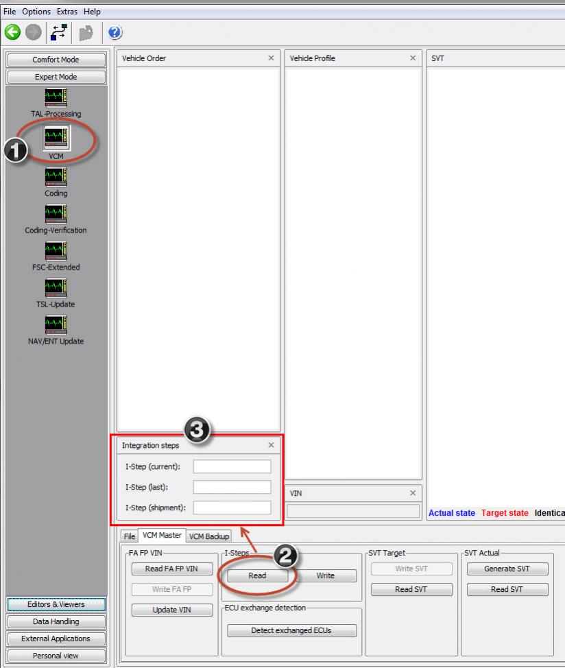
- To find this, go to the Expert Mode-VCM Screen. Under I-Steps, click Read. Your current I-Step level will then be displayed, as shown below. Take down this information, and save for future reference if needed.
SHOWN FOR ILLUSTRATIVE PURPOSES ONLY:
- Now, you can create the Cafd file. On the Expert Mode-Coding screen, if you click Read (ECU), you should now see the PMA listed as one of the modules on your car. However, it will most likely be missing the Cafd file. Highlight the PMA, then click Detect CAF for SWE. When the window shown below comes up, you may have several options available:
SHOWN FOR ILLUSTRATIVE PURPOSES ONLY - NOT ACTUAL PMA MODULE CODING:

- You will need to select the option that matches your car’s current I-Step Level. Select the correct option and hit Ok. This should create the Cafd file for the PMA.
- Now all that is left is to VO Code the updated FA to the car. Activate the FA. At this point, you will need to code the DSC, REM, HU_CIC/NBT, TRSVC, ICM, and PMA modules. Personally, whenever I complete a retrofit, I recode all modules in the car in the event that there is something related to the new retrofit in that module that may have been missed. How you code is up to you, but by coding them all, it avoids the risk of missing something.
Reassembly of the car:
Once you have completed all coding, turn the car off, then back on. You should now see the Parking Assistant option when you press the PDC button on the center console, as well as the “P” icon when it is turned on. Assuming all checks out with no errors, you can re-assemble all of the trim panels/trunk lining and reattach the front bumper to the car.
DON’T FORGET to apply sealant to the wiring access point in the firewall!!!
Testing the system:
In order to test the system, you will need to spend some time driving around and learning how the system works. I recommend accessing the On-Screen Owner’s Manual in the car, watching the Video and reading all of the information the manual provides about the system before you begin using it. Once you are ready to hit the road, I suggest finding some open areas with a decent curb first in low-traffic areas where you will be able to “practice” parallel parking with the system without being interrupted by other traffic. Even without other nearby cars, the system will often detect areas to park that will allow you to get a feel for the turning radius, etc. Once you have this mastered, find some areas with parked cars that you can test the feature out, remembering of course to be careful as there is a bit of a learning curve.
Notes/Observations from use:
I have found that the system can sometimes be finicky about the spots it will try to put you in. For example, it will find open spots, but if it doesn’t detect the curb correctly, I will have to stop the maneuver and try again. Also, there are times when I was testing the system where I saw a clear spot, thought “Oh awesome, there is a perfect spot to test it!”, but the system decided otherwise and did not detect it. Likewise, there were some smaller spots that it said were open, but I decided against trying it as I thought “there is no way I will fit in that spot.” Lastly, as I was trying to test it in open areas with no other cars, it would not detect very many spots, which I attributed to the fact that since the space was wide open with no other cars to detect, it would not show spots available since it figured I had enough room to park myself lol.
Congrats! You now have an assistant to help you with parallel parking the car, and hopefully you had the same results as below!


 , F85 ACC Retrofit


